
The Mini Kossel delta 3D printer is available in kit form from various suppliers, including Think3DPrint3d (T3P3) in the UK. The kits currently supplied by TPT3 include an Arduino Mega and a RAMPS board to control the printer with Marlin firmware. Although this combination can drive the Mini Kossel, a number of delta 3D printer owners have commented that this combination of electronics and firmware is barely able to handle the demands of a delta printer and attached LCD display. Users who have attempted to add a 128×64 graphics display have reported very poor performance of the display while printing.
Today, 32-bit embedded processors are cheap. So there is no longer any reason to use 8-bit controllers to drive 3D printers. A few 32-bit controllers boards are available, including the Smoothieboard and the Duet. The Smoothieboard has been described elsewhere. In these articles, I will describe how to upgrade a Mini Kossel built from a T3P3 kit to use Duet electronics and associated firmware. This article describes the hardware, and the following article will describe software configuration and commissioning.
Note that the Duet firmware does not support the Panel One LCD control panel supplied with the T3P3 Mini Kossel kit. If you want to run your Mini Kossel with Duet electronics independently of a PC, I suggest my own PanelDue colour touch-screen control panel, see https://miscsolutions.wordpress.com/paneldue/.
This post is work-in-progress, and is likely to be updated in the light of further experience.
Duet electronics
The Duet electronics is a 123mm x 100mm all-in-one 3D printer control board with the following main features:
- ATSAM3X8E processor (ARM Cortex-M3 core) running at 84MHz, with on-chip Ethernet and USB
- Four A4982 stepper motor drivers, supporting 1/16 microstepping. The A4982 is similar to the popular A4988, but the package variant used in the Duet has better thermal characteristics than the A4988, so it can be used at slightly higher currents.
- Digital control of stepper motor currents
- Power mosfets to drive heated bed, one hot end, and a controllable cooling fan
- Ethernet and USB ports
- Input voltage range 12V to 35V
- Optional switching regulator to provide 5V supply, and linear regulator to provide 3.3V supply from the 5V supply
- SD card socket
- Ethernet and USB ports
- Expansion connector to allow connection of extensions and daughter boards, such as the DuetX4 expansion board, the RepRapPro additional hot end shield, and the PanelDue
- Similar architecture to the Arduino Due
Duet electronics runs RepRapFirmware. Several forks are available, including mature versions that support an on-board web server as well as the usual USB interface.
Parts needed
- Duet electronics board. If possible, get one with header pins for the motor and endstop connections rather than screw terminals (see next section).
- Stepper motor looms. If you want to make things easy and avoid some soldering, get at least two, each at least 450mm long. Otherwise, you will need to cut and splice the existing looms, so check that you have some suitable heatshrink sleeving.
- Duet enclosure: print this before you dismantle your Mini Kossel.
- 100mm cable ties, unless you have plenty left over from your Mini Kossel build.
- USB-A to Micro USB-B cable, to connect the Duet to your PC.
- Micro SDHC card. 4Gb capacity is plenty.
- 4-way and 2-way 15A chocolate-block connector.
- 225mm of 15A 2-core polarized cable, for example heavy-duty speaker cable.
- 225mm of 10A 20core cable, for example speaker cable.
- Two 6mm M3 countersunk screws.
- Four short (approx. 8mm long) 3mm self-tapping screws to secure the Duet.
- Two long thin self-tapping screws or woodscrews, to mount the chocolate-block connectors.
- One 3-way 0.1″ pitch header shell.
Get a Duet with suitable connectors
Duet boards can be purchased from Think3DPrint3d (http://www.think3dprint3d.com/Electronics/electronics-boards/Duet) and RepRapPro (https://reprappro.com/shop/components/duet-pcb/). [EDIT: now from http://www.replikeo.com/en/3d-printer/duet-board as well.] Boards from TPT3 generally have screw terminals for making most of the connections, whereas boards from RepRapPro use header pin strips or (on later boards) Molex connectors. This image shows a typical T3P3 board on the left, and a board more like a RepRapPro board on the right.

The Mini Kossel kit from T3P3 uses header sockets to terminate the looms from the stepper motors and endstop switches. So a Duet with header pins is more easily used with a T3P3 Mini Kossel kit.
I had a Duet from T3P3 to use with my Mini Kossel, and it came with screw terminals. I could have cut off the header sockets on the wiring looms and wired them into the screw terminals; but I prefer the quick-disconnect facility provided by a plug and socket. I tried clamping header pin strips in the screw terminals, but the short pin sides of the header strips were not long enough to be held in the screw terminals reliably. So the right hand board in the above image is actually a Duet from T3P3 after I removed the screw terminals from the bottom row and replaced them with header pin strips. The screw terminals were all 2- and 3-way, so I was able to do this quite easily using SMD desoldering tweezers to heat the outer 2 pins, and a soldering iron to heat the middle pin of the 3-way terminal blocks.
 The hot end heater loom in the Mini Kossel kit is designed for use with screw terminals as on the RAMPS board. However, the hot end connector on the Duet comprises two pairs of screw terminals or header pins, intended to be used with doubled-up heater wires. I had to remove the screw terminals anyway, because the rightmost terminal of the four was part of a 3-way terminal block, and I wanted to replace the other 2 terminals with a 2-way header for the hot end thermistor. So I reinstalled one of the 2-way screw terminal blocks in the middle two connections. To help share the load between the PCB vias, I added wire links on the back of the board from the two unused holes to the pins of the
  terminal block.
I also replaced the 2-pin bed temperature terminal block by a 2-pin header.
Check that all 4 lugs of the micro USB connector have been soldered to the board. In this photo, the bottom 2 lugs had not been soldered.
If the Duet becomes a popular option for the mini Kossel, perhaps T3P3 will offer a version of the Duet with header pins for the motors, endstops and thermistors.
Where to mount the Duet?
The Arduino/RAMPS combination fits underneath the bed of the Mini Kossel. Although the Duet board has less depth than the Arduino/RAMPS combination, it is too wide to fit between the stepper motors supplied in the T3P3 kit. These stepper motors are 47mm deep, compared to 33mm for the steppers used in my Duet-powered Ormerod. So it might be possible to use shallower stepper motors in the Mini Kossel, if they provide sufficient torque; and then I think the Duet would fit under the bed.
Another possibility would be to increase the lengths of all nine top and bottom extrusions by 15 to 20mm, turning it into a Midi-Kossel.
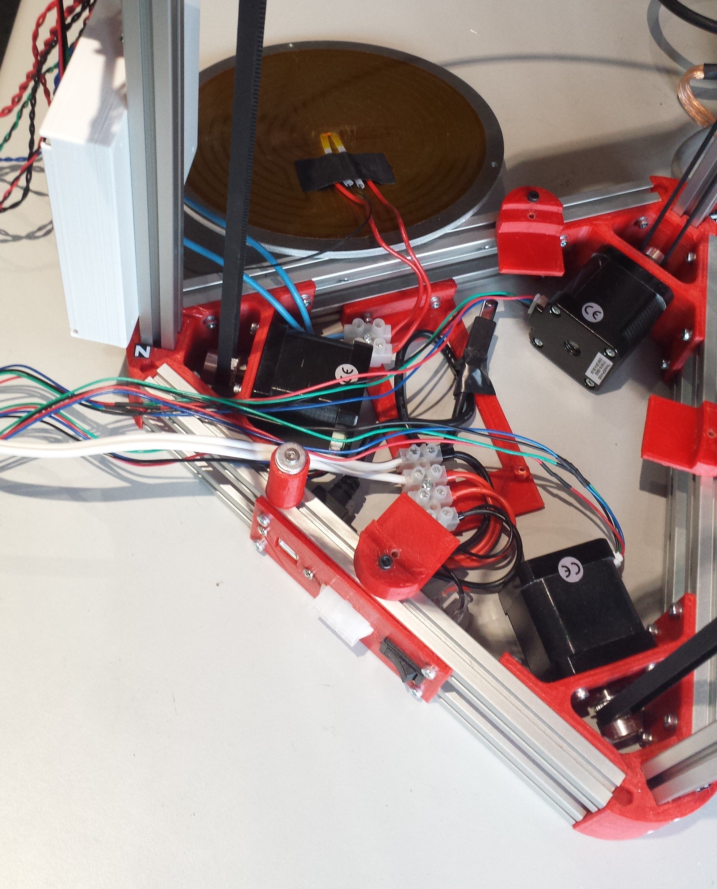
 With the original stepper motors and extrusions, the Duet needs to be somewhere else. The place I selected was on the back of the Z tower, below the extruder drive. The enclosure design I printed can be downloaded from http://www.thingiverse.com/thing:441075.
Preparing the Mini Kossel
Disconnect and remove the RAMPS and Arduino. Remove the electronics cooling fan if you fitted one, or disconnect it and tape the wires securely out of the way. Tape the black USB cable out of the way.
The Mini Kossel power loom provides two pairs of 12V wires to feed the RAMPS. Only one pair is needed by the Duet. The power loom is too short to reach the Duet, so terminate it in the 4 way chocolate block connector. Secure the connector to the tray that the Arduino was mounted on, using a long thin screw.
The next step is to make all the looms reach the position near the bottom of the Z tower where the Duet will be mounted.
Stepper motor looms
Of the three tower motor looms, only the Z loom will reach the Duet, while the extruder loom is much longer than required. So disconnect the X, Y and extruder stepper motor looms. Plug the X or Y loom into the extruder stepper motor. To avoid confusion, either re-label its connector ‘E’, or remove the connector pins from the header shells and swap the header shells over.
This leaves you with one very long loom (which was the extruder loom) and one short loom. If you didn’t buy new looms, you need to convert these into one loom about 450mm long for the X motor, and another about 350mm long for the Y motor. To achieve this, cut 50mm off one end of the short loom, and 220mm off the same end of the long loom. Then splice those ends on to the opposite cables, using solder and heatshrink sleeving.
Endstop looms
 The endstop looms on the Mini Kossel kit terminate in the centre pin and an outside pin of a 3-pin header socket. The Duet provides a 3-pin header for connecting each endstop, but it expects the endstop microswitches to use the two outer connector positions (and it doesn’t matter which way round you plug it in). So for each of the 3 endstop looms, you need to move the centre receptacle in the header sockets to the spare outside one. This
 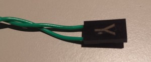 is quite easy to do, you just need to lift the plastic barb with a tiny flat-bladed screwdriver or fine tweezers so that you can pull the receptacle out of the shell, then re-insert it in its new position. The upper image shows the Y endstop connector as it was originally, and the lower shows it after modification.
The Y endstop loom will only reach the Duet without being extended if you re-route it. Route it across the top of the frame to the top of the Z tower, then down the Z tower, following the route of the Z endstop loom. I routed the X endstop loom the same way, but it may not have been necessary.
Other looms
Modify the Z probe microswitch loom to use the outer two connectors, in the same way as for the endstop looms.
The hot end fan connections are terminated in a 2-way header. The header shell needs to be changed to a 3-way header shell for the Duet, using the outer 2 positions).
 Run 225mm of the 2-core 15A cable from the power connections on the chocolate block connector to where the Duet will be. Connect to the doubled-up thick red and black wires from the power connector, because these can carry more current than the single wires can.
The heated bed wires are too short to reach the Duet. Position the heated bed so that the bed thermistor wires will reach the Duet, then terminate the heater wires in the 2 way chocolate block connector. Secure the connector to the mounting tray, and run 225mm of 2-core 10A cable from this connector to the back of the Z tower.
Replace the bed insulator and heated bed. All the looms should now have their free ends near the bottom of the Z tower, where the Duet will be mounted.
Mounting the Duet
Check that the enclosure has all the necessary cutouts to access the connectors and the SD card socket
 Remove the extruder drive assembly from the Z tower and drop a couple more M3 nuts into the rear slot of the extrusion. Re-fit the extruder drive assembly, leaving 2 nuts below it. Secure the Duet enclosure to those nuts using 6mm M3 countersunk screws. The cutouts for the SD card slot, USB port and Ethernet port should be at the top, and the power input and heated bed cutouts will be at the bottom. Check that the screw heads are seated fully into the countersinks in the enclosure, and put some tape over them to avoid any risk of shorting the back of the Duet board.
Now attach the Duet to the enclosure using four short self-tapping screws.
Wiring
Connect the power wires to the Duet power-in terminals, taking great care to get the polarity right. There is a large + sign on one side of the Duet power input terminal block (the side nearest the stepper motor headers), and this must be connected to the red wire in the Mini Kossel power loom.
 Connect the heated bed wires to the heated bed terminal block, and connect the heated bed thermistor to the BED_TEMP header pins next to it.
Connect the X, Y and Z motor looms to the positions indicated on the Duet, and the corresponding endstop looms next to them. The motor looms must be connected the right way round (red wires at the top – this is the opposite way round compared to using the Duet on an Ormerod), otherwise the motors will run backwards. Connect the E motor loom to the position indicated on the Duet, with the Z probe connector next to it.
Connect the extruder heater wires to the corresponding terminals on the Duet, and the extruder thermistor next to it.
Finally, connect the hot end fan wires as shown in the photo, ensuring correct polarity.
Part 2 will cover firmware, configuration, and commissioning.
Update
 During commissioning, I decided that I didn’t like having the Ethernet and USB connectors at the top of the enclosure. So I updated the enclosure design to include extra mounting holes so that I could mount it horizontally. I had to extend the heated bed thermistor wires and the extruder loom. So this is what it looks like now. Unfortunately, the extruder motor transmits vibration through the Z-tower extrusion, and with an extrusion rate of 5mm/sec this triggers a resonance in the enclosure with the Duet mounted in it. I mostly got rid of this by putting a piece vibration-deadening material between the enclosure and the tower extrusion, and another between the extruder mount and the tower extrusion. If I modify the enclosure design again, I will either increase the base thickness back to 3mm, or add some ribs to reduce its tendency to vibrate.
Acknowledgement
Thanks to Think3DPrint3D for providing the Mini Kossel kit and Duet board for this project.

Pingback: Ormerod and Mini Kossel 3D printer kits compared | David Crocker's Solutions blog
Pingback: Building a large delta 3D printer | David Crocker's Solutions blog
Hello again David.
Regarding your heated bed, are you using the normal bed output of the Duet to drive the SSR?
As I also have a 110V heater, I was looking on saving this fet for a fan and drive the SSR using other PWM pin of the Duet (again, as I’m doing right now with RAMPS).
Yes, I am using the normal bed output terminal connector block to drive the SSR.
Great Job! Thank you so much, great work with the web interface, I’ve been using this machine for about 5 months great quality. I’ll try to take some time to check the project code for updates.
Thanks! The current web interface isn’t my design, it’s by Christian Hammacher, aka zombiepantslol on the Reprap forums.
Hi David,
How does one connect optical endstops to Duet 0.8.5? Apparently centre pin on Duet is not used. My endstops have three connectors – G, VIN and SIG. I checked with a multimeter and SIG goes high (3.1 or so V) when endstop is triggered. Otherwise it outputs few mV only. The endstop seems to work OK when powered with 3.3V.
If you look on the back of the Duet, you will see that the endstop pins are labelled GND, 3V3 and STP. Connect those to G, VIN and SIG of your endstop respectively. You may need to reduce the value of the LED series resistor in the endstop to get enough sink current when it is powered from 3.3V.
Thanks David, works perfectly. And without changing the resistor.
All the fans I have on hand are 24v, and I wired up my print cooling fans, only to discover that my Duet 0.6 is putting out 5.5v on the fan0 header. Is there some way to wire it up to run off 24v and still be controllable? Or do I need to find some 5v fans?
If you are using 24V power then the Duet 0.6 puts out 24V on the FAN0 output. So either you have a bad connection in your wiring, or a fault on your Duet.
Pingback: 7 Best DIY 3D Printer Kits In 2018 - ShapeGadgets