
The Ormerod Hot End Board V2 from Escher Technologies integrates the following functions:
- Differential modulated IR height sensor. The sensor detects the target height by looking for the reflected light from two separate LEDs to be equal. The two LEDs are positioned such that they reflect light into the sensor at slightly different heights. This allows the sensor to be used on almost any bed surface – white targets are not needed.
- The height sensor is approximate in line with the nozzle in the X-direction, so that it is less affected by head sag than the standard sensor mounted on the X-carriage.
 Backup mode (simple modulated IR sensor).
- High degree of immunity from sunlight, incandescent artificial light and other background sources of IR.
- Illumination of the area under the print head, using white LEDs with constant current drive so as to be unaffected by variation in the 12V (or higher) supply.
- Reliable heater, fan and thermistor connectors on the board, with crimp receptacles that can be removed from the shells without difficulty.
- Hot end fan control (fan is turned off when the extruder is cold).
- Amber LED to indicate when the heater is powered.
- Red LED to indicate when the head is at or below target height.
The board is supplied fully assembled.
 Boards supporting 2-nozzle printers are also being made. These are similar to the standard board but monitor the temperatures of two nozzles to determine whether to turn the fan on. Compared to the standard board, they are wider at the top to accommodate extra connectors for the second thermistor, heater and wiring loom, and a second amber LED to indicate when the second heater is powered. The instructions for installing the dual-nozzle boards are the same as for the standard boards except where noted in the text.
Warnings – read this before installing!
- Make sure you connect the wires from the Ormerod to the correct connector pins! Otherwise you may damage the Duet and/or the sensor board.
- Do initial testing using USB power only, as described in the section on commissioning.
- Make sure that the sensor board cannot short against the Z threaded rod if driven beyond the X homing position! Print and fit the recommended insulating part.
- Do not power up the hot end heater without having the 4-way sensor connector securely fitted in place. The 4-way connector carries the +3.3V and 0V power lines from the Duet, which must be connected for proper operation. Otherwise, the fan may be off even if the hot end is on, which could cause the plastic hot end parts to melt.
- Before dismantling your Ormerod hot end, print the replacement parts needed to accommodate the new sensor board.
Tools required for assembly
- 1.5mm allen key or hex driver (for the M2.5 countersunk screws supplied with the board)
- Crimp tool (not essential, but highly recommended). Type HT-225D is suitable and inexpensive. It is available from various eBay suppliers, and from Rapid Electronics in the UK.
Preparing the Hot End Board
1. As shipped, the board is configured to assume that the thermistor series resistors on the Duet have a value of 1K. However, on later production Duet boards this was changed to 4.7K and a sticker is placed on the board to advise you of this. If your Duet has 4.7K thermistor series resistors, you must bridge the pads labelled R24 on the hot end board. Please observe the usual antistatic precautions when doing this. If your board already has a resistor installed at position R24 then it is already configured for use with a 4.7K series resistor, and you must remove it if you are using the board with 1K series resistors.
If you have a dual nozzle board and you will be using it with two nozzles, then both series resistors must have the same value. You will have one of the following setups:
- Original Duet with 1K resistors, and Duet X4. In this case, all series resistors are 1K.
- Duet with 4.7K resistors, and Duet X4 (which has 1K resistors). In this case, I suggest you swap the hot end thermistor connections with the extruder 2 connections, so that both hot ends use 4.7K series resistors. This also alleviates the noise issue with the thermistor channel on the DueX4. You need to bridge R24, and use the X parameter in the M305 commands in config.g to tell the firmware about the thermistor channel swap (i.e. M305 P0 X2 and M305 P2 X0). Also change the M305 P0 command to specify that the bed thermistor series resistor is now 1K.
- Original Duet with 1K resistors, and Duet shield (which has 4.7K resistors). I suggest you connect the heater 1 thermistor to the heater 3 thermistor input, so that both heaters use 4.7K thermistor series resistors. You will need to bridge R24, and include command M305 P1 X3 in config.g to tell the firmware about the change.
- Duet with 4.7K resistors, and Duet shield. In this case, all series resistors are 4.7K. You need to bridge R24.
Note: the X parameter to the M305 command is supported by my firmware fork, but not in the current (1.04) version of the original RepRapPro firmware.
2. The newer version of the dual nozzle board has a pair of jumper pins next to the thermistor 1 connector. The board is supplied with a jumper across these pins. Leave the jumper in place to use the board with a single nozzle. Remove the jumper to use it with 2 nozzles.
Preparing the Ormerod
1. Download and print the following printed parts (you can also find the OpenScad models for them at https://github.com/dc42/OrmerodSensorBoard/tree/master/PrintedPartsForSensorBoard): 
- Modified heatsink duct (see photo), or modified one-piece heatsink/fan duct. If you are installing a board on a dual-nozzle print head, then you should use the version of the heatsink duct with longer standoffs so that the sensors on the board are not too close to the nearest nozzle. If you use the one-piece heatsink/fan duct, then you will need to turn the heatsink through 90 degrees, and drill another hole in the heatsink for one of the mounting screws. If you have the newer Ormerod 2 that has an acrylic spacer for the hot end instead of the heatsink duct and the fan duct, then I suggest you print the one-piece duct (and drill the extra hole in the heatsink). If you decide to design your own part instead, make sure it has the two holes for mounting the hot end board, and a cable tie post to provide strain relief for the cables.
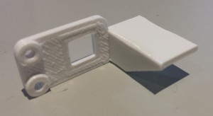
- Add-on sensor pad (see photo).
 Sensor board insulator (see photo). If you are installing the board on a dual-nozzle print head, use the version with shorter standoffs, to compensate for using a modified heatsink duct with longer standoffs.


If you are upgrading from the version 1 hot end board and using a single-nozzle print head, then you need only print the insulator.
2. Check that all holes in the printed parts are the correct size and fettle if necessary. The 2.5mm countersunk screws supplied with the board should clear the holes in the insulator and self-tap into the holes in the heatsink duct. The two round holes in the sensor pad should also be M2.5 clearance.
3. Position the Ormerod print head well clear of the bed to make dismantling and commissioning easier.
4. Disconnect the Duet USB cable and the power supply mains cable.
5a. Check that the aluminium heat spreader is not shorting against either of the connections at the front of the heated bed. This can occur if the heat spreader is installed upside down on the Ormerod 1, which is an easy mistake to make.
5b. Preferably, put a sheet of black paper or thin black plastic between the aluminium heat spreader and the glass bed. This is not essential, but improves the accuracy of the sensor. It s not necessary if you have covered the glass bed with an opaque material such as BuildTak.
6. Disconnect the sensor wiring loom from the old IR sensor. Remove the IR sensor from the X-carriage.
 7. Attach the add-on sensor pad to the existing X motor mount, using the two M2.5 screws that previously held the IR sensor in place (see photo). Unless you printed the sensor tab in white, you may need to attach a piece of white tape or white paper on the top of the homing tab.
8. Cut off the 6-way connector from the Ormerod hot end loom. Strip the ends of the 8 cut wires and attach the crimp receptacles supplied. Push the receptacles into the 8-way header shell, ensuring they are in the correct positions.
For Ormerod 1, the colours are as shown in the photo (below). Some Ormerod 1 looms use a pink wire as in this photo, but other looms use a red wire in place of pink. Likewise, some Ormerod 1 looms use 2 brown wires as shown, while others use 2 orange wires instead.
 For Ormerod 2, the order of the colours on the 8-way connector is, from left to right: black, purple, red, brown, yellow, white, blue, green.
If you push the crimp receptacles into the wrong position, they are quite easy to remove; just push a very small flat-bladed screwdriver or similar tool into the slot to disengage the barb, then you can pull them out.
9. The 4-way connector is for the sensor loom. Cut off the existing 3-way (Ormerod 1) or 4-way (Ormerod 2) sensor connector from the sensor loom, strip the ends of the wires, attach the crimp receptacles supplied, and push them into the correct positions in the 4-way shell.
For the Ormerod 1, the photo shows the correct colours. Ignore the yellow wire on the 4-pin connector in the photo. Your wiring loom may have a red wire instead of the pink wire shown. For the Ormerod 2 the order of the wires on the 4-way connector is, from left to right: blue, red, yellow, green.
10. If you are fitting the board to an Ormerod 1, you can optionally add a 4th wire back to the Duet. You only need this wire if you want to be able to use the backup mode (simple modulated IR sensor), for example if you have difficulty with x-homing when using the differential IR sensor. This wire (yellow in the photo) goes from the left-most position of the 4-pin connector on the hot end board to the Duet expansion connector. If you are using firmware version 0.78 or later, it goes to pin 41 (see diagram here). If you are using older firmware, it goes to pin 34, which is the one immediately above pin 33 that the blue wire is connected to.
If you have an Ormerod 2, then you already have this 4th wire in the sensor loom (it is the blue wire).
11. Cut the thermistor, fan and cartridge heater wires close to the original 6-pin hot end connector. Strip the cut ends and attach crimp receptacles. Then push the receptacles into the three 2-way shells supplied. The polarity of the thermistor and cartridge heater wires is unimportant, but the red and black (or blue) wires from the fan must be the right way round (see photo in next section). If you are using a dual-nozzle board on a single-nozzle machine and your board does not have the jumper pins next to the thermistor 1 connector, when attaching crimp pins to the thermistor wires you must also crimp one end of a short loop of wire into the left hand pin. The other end of this wire goes to the left hand pin in another 2-pin receptacle, which will be plugged in to the Thermistor 2 connector on the board.
 12. Dual-nozzle boards only: the 6-way connector on the board is for the second hot end loom. This carries the heater wires (two yellow and two brown or orange) from the DueX4 board or Duet shield to the second nozzle heater, and the thermistor wires (blue and green) for the second nozzle thermistor. Fit crimp pins and the 6-way shell to the second hot end loom as shown in the photo. If you are using an 8-way hot end loom similar to the Ormerod 1 main hot end loom, leave the red (or pink) and black wires disconnected at both ends.
Also fit crimp pins and 2-way shells to the wires from the second cartridge heater and second thermistor.
 Fitting the board
1. Remove the hot end from the nozzle mount and dismantle it by removing the two screws that hold the fan, printed parts and heatsink block together.
2. Place the insulator on top of the hot end board, then attach both to the replacement heatsink duct that you printed, using the 2.5mm countersunk screws supplied (see photo).
 3. Check that the IR LEDs (D5 , D6) and phototransistor (Q2) are sitting perpendicular to the board (see photo).
4. Reassemble the hot end. If you are using the original fan duct, you will need to cut off the cable tie loop to clear the board. If you are using the one-piece heatsink/fan duct,  then you need to rotate the heatsink 90 degrees and drill a new hole in it for one of the mounting screws.
5a. Standard (single-nozzle) boards: Plug the fan, thermistor and heater connectors into the three 2-pin connectors on the board as shown in this photo. The top left connector is for the cartridge heater (thick red wires), bottom left is for the fan (red and blue wires, but may be red and black on your fan), and the bottom right connector is for the thermistor (green and blue wires).
5b. Dual nozzle boards: Plug the fan connector, 2 heater connectors and 2 thermistor  connectors into the correct 2-pin connectors. The connectors are labelled on the back of the board and are also shown in this photo. The connectors for the main hot end loom, sensor loom, nozzle 1 cartridge heater and nozzle 1 thermistor are in exactly the same positions as on the single-nozzle board.
You can choose which heater/thermistor combination to connect to heater 1/thermistor 1, and which to connect to heater 2/thermistor 2.
6. Check that the nozzle mount is attached the X carriage the right way up, with the bevelled edges underneath. Then re-attach the hot end to the nozzle mount.
7. Plug the 4-way sensor loom connector into the board.
8. Plug the 8-way hot end loom connector into the board. If you have a dual-nozzle board and you are installing it in a dual-nozzle printer, also plug the 6-way second hot end connector into the board.
9. Important: cable-tie the hot end and sensor looms to the cable tie point on the heatsink duct. Otherwise, the constant flexing of the wires as the head travels along the X arm will cause the wires to fracture where they enter the crimp receptacles.
Commissioning
 1. Do the following checks:
(a) Check that the wires in the sensor harness from the Duet board are connected to the correct pins on the 4-way connector as shown in these photos. If you get the wires in the wrong order, you may damage the board. In this photo, we have unplugged the cartridge heater and the 8-way hot end loom connector. The photo shows an Ormerod 1 wiring loom with a yellow 4th wire added. So for an Ormerod 1 the colours of the wires going into the 4-way connector should be, from left to right: yellow (or white, or whatever colour you used for the 4th wire, or not present), blue, black, pink (or red). For an Ormerod 2 the colours going into the 4-way connector should be, from left to right: blue, red, yellow, green. The pins are also labelled on the SMD side of the sensor board with the voltages and signals that they carry.
(b) Check that the wires in the hot end loom from the Duet board are connected to the correct pins as shown in the photo below left for a standard board, or below right for a dual-nozzle board. Warning: if you mix up the thermistor wires with the other wires, you will damage the Duet, the sensor board, or both. [This also applied to the original 6-pin connector.] If you swap the fan + and – wires, you will damage the board. On an Ormerod 1, from left to right the colours in the 8-way connector are: yellow, yellow, brown (or orange), brown (or orange), pink (or red), black, green, blue. The colours in the secondary hot end loom on a dual-nozzle board are in the same order, except that the black and red (or pink) wires are not present. On an Ormerod 2, from left to right the colours on the 8-way connector are: black, purple, red, brown, yellow, white, blue, green.


(c) Check that the cartridge heater is pushed all the way into the aluminium block (it may have been partially pulled out when you connected it to the board). Also check that the thermistor is still central in the aluminium block.
(d) Check that when the X-carriage is moved all the way towards the Z-axis, the board cannot short against the z-threaded rod or other metallic parts. The insulator should stop against the Z-nut trap before that can happen.
(e) Check that there is enough travel in the X-axis for the IR sensor head to go over the X-homing tab. If necessary, extend the sensor pad in the +X direction using a piece of white card or white self-adhesive label.
2. Power up the Duet using USB power only. Do not connect the 12V power supply yet.
3. Send command M558 P1 to tell the Duet to enable the sensor (not necessary if you already have exactly this command in config.g).
4. Assuming the head is well clear of the bed, the G31 reading should be close to zero, and the red LED on the edge of the board should be off. Note: although the modulation greatly reduces the effect of ambient light, very strong ambient light (such as direct bright sunlight falling on the bed under the sensor head) can still saturate the sensor. If the board detects that the sensor is saturating then it produces a G31 reading close to 1023 and the red LED illuminates.
 5. Position a suitable target (e.g. a sheet of glass) horizontally under the head, then gradually move it up towards the sensor head. At a point about 3mm below the bottom edge of the board, the red LED on the side of sensor board should light up (see photo), indicating that the trigger point has been reached. The G31 reading will increase to about 535. When you lower the glass again, the LED should turn off and the reading should drop back to near zero. If this is not working properly, do not apply 12V power, check your connections instead.
6. Apply 12V power. There should be no signs of overheating, and the lighting should be on. The fan should not be on, unless the reported hot end temperature is above 40C or below -5C. If it is on with the nozzle cold, then turn off the power, disconnect the USB cable, and check that the thermistor wires in the Ormerod hot end loom are connected the right way round at both ends.
7. Send M558 P1 again (unless you have this command in config.g already), then send G31 P500 Z1.0.
8. With the nozzle at least 5mm above the bed, command the head in the -X direction, looking to see if the red LED illuminates when the sensor is over the homing pad. If it doesn’t, then try extending the homing tab a little in the +x direction by attaching a piece of white card or a white self-adhesive label to it. If it still doesn’t work, then you can further adjust the size, height or surface of the homing tab so that the differential sensor is triggered. Or, if you added the 4th wire back to the Duet or you have an Ormerod 2, you can engage backup mode (simple modulated IR sensor) by sending command M558 P3 and use this mode for x-homing instead.
Once you have the LED illuminating when the sensor is over the sensor pad, test that homing the X axis works. Note: if you have an Ormerod 2 and you are using the standard RepRappro homing files, then you will need to modify the homex.g and homeall.g files. Open each of these files in a text editor, locate the “M558 P2 lines, comment them out by putting a semicolon at the start of the line, and save the file. Also change M558 P2 in your config.g file to M558 P1. The board must always be run in differential LED mode (P1) or simple modulated mode (P3). If you select P2 then the board will be asked to switch rapidly between modes and you will not get a sensible reading.
9. To calibrate the sensor for Z homing and bed probing, home X and Y, then position the head over the centre of the bed. Lower the head so that it is just touching the bed or just gripping a sheet of paper, then send G92 Z0. Now raise the head in 0.05mm or smaller steps, until you find the greatest height at which the G31 reading is about 535, and it drops to about 465 if you raise it another 0.05mm. Read off the Z height and use that value in your G31 command. For example, if the G31 reading is 535 at 1.30mm and 465 at 1.35mm, then the command you need in config.g is: G31 P500 Z1.30 Note: (a) Always use a P value of 500. That way, when the Duet sees the reading of about 465, the firmware can tell that it is getting close to target height and (depending on what firmware you are using) it may slow down the Z motor. (b) The G31 command in config.g must come after the M558 P1 command. This is because the some versions of RepRapFirmware support different G31 values for different sensor types.
10a. Test the fan control and heater LED:
a) Remove both USB and 12V power, unplug the 2-pin thermistor connector from the sensor board, and reapply power. The Duet firmware should show -273.2C (indicating a temperature fault) and the fan should be on.
b) Remove power again, reconnect the thermistor, and power up. The fan should be off, provided that the ambient temperature is no lower than -5C.
c) Command nozzle 1 to 50C. Caution: if you have used the M305 X parameter to remap thermistor channels, then watch the temperature on the web interface or Pronterface to make sure it is responding. If the temperature reading does not rise as expected, switch off the heater immediately – you may have the firmware configured to monitor the wrong thermistor. The amber LED should illuminate, and the fan should come on when the reported extruder temperature exceeds about 42C. As the temperature approaches 50C and the Duet starts applying PWM, the amber LED will dim.
d) Command nozzle 1 to 0C. The amber LED should go off, and the fan should go off at about 38C.
10b. If you have a dual-nozzle board, repeat step 10a for the second nozzle, with the first nozzle at room temperature (below 35C).
11. Set up bed compensation. Establish 4 automatic bed compensation coordinates that place the sensor head about 25mm in from the corners of the bed and not close to the bed clips. These will not be the same as your previous ones, because of the new position of the sensor. Put these coordinates into the M557 entries in your config.g or setbed.g file. If you were previously using white paper, white tape or aluminium tape targets for bed compensation, remove them. The differential sensor works best on plain glass, or Kapton tape on glass, or solvent cement on glass. Some firmware versions support a 5th bed compensation coordinate, which you should define close to the middle of the bed, at the centre of the other 4 coordinates.
Note: when using bed compensation, after executing the G32 command with fewer than 5 points, it is recommended that you home the Z axis again, so that the Z height is accurate at the centre of the bed.
12. Edit the homing files (optional)
a) Edit homez.g and homeall.g files to change the Z homing XY coordinates to be at the centre of the bed instead of in one corner.
b) If you are using backup mode for X homing, then edit homex.g and homeall.g to add command M558 P3 at the start of the X homing sequence and M558 P1 at the end of it.
Troubleshooting
Symptom: Fan does not turn off when the nozzle (both nozzles on a dual nozzle system) is cold.
Causes:
(a) The thermistor wires between the hot end board and the Duet are the wrong way round. Try reversing the 2-pin thermistor connector where it plugs into the Duet or Duet shield. In dual-nozzle systems, both sets of thermistor wires must be the right way round for the fan to turn off, so try reversing them one at a time.
(b) Your Duet/Duet shield uses 4.7K series resistors, but you have not connected a wire link at position R24. Or you have connected a wire link at R24, but your Duet uses 1K series resistors. See section “Preparing the hot end board” near the beginning of these instructions.
(c) The 12V + and – wires to the hot end board are the wrong way round. Do not reverse these wires unless you are sure that you have connected them the wrong way round! Reversing these wires will burn out mosfet Q1 on boards that have diode D4 fitted, and may damage the mosfet on boards without D4.
Symptom:
The hot end board collides with the sensor pad when you try to home the X axis, instead of riding over it.
Causes:
(a) You have installed the nozzle mount upside down on the X carriage. The bevelled edges go at the bottom.
(b) You are using a longer than normal nozzle mount, or an extra spacer between the nozzle mount and the hot end assembly.
Options and modifications
Alternative lighting
If you wish to use your own lighting (e.g. LED strip) then you can connect 12V lighting to the pads provided for this purpose, labelled +12V and 12VGND. Alternatively, remove the three white LEDs from the board and run wires from the LED pads to your own 20mA LEDs. The LED current can be increased above 20mA by adding a 0603 size resistor at position R1, but if you do this, refer to the BCR402U chip datasheet to determine the correct value, and be careful not to exceed the power dissipation rating of the chip.
Using with higher voltage power supplies
As supplied, the board is suitable for use with a fan and extruder heater supply of 11-14V and a sensor board supply of 3.3V. If your printer use a higher voltage supply (e.g. 24V instead of 12V nominal) then you must increase the heater LED series resistor R8 (and also R11 on dual-nozzle boards). This is a 0805 size power resistor, with a value of 470 ohms for 12V nominal supply voltage. For 24V operation, we suggest you use a 1.2K 0.5W 0805 power resistor. Other components on the board are already suitable for 24V operation (the fan control mosfet is rated at 30V and the constant current LED driver at 40V).
To use the board with a 5V supply (e.g. as on older versions of the RepRap Mendel) instead of 3.3V, you might want to increase the infrared LED series resistors to reduce the forward current and prolong the life of the LEDs. R2 should be increased to 130 ohms, and R3 should be increased to 200 ohms. Preferably, also increase R1 to 4.3K to maintain sensitivity. These are 0603 1% tolerance resistors. However, it is likely that the board will give years of service when run from 5V even without any component changes. Later production boards (March 2015 onwards) already use somewhat higher value resistors, so they should be fine on 5V as supplied.
Changing the firmware
The firmware for the ATtiny44a microcontroller was built using Atmel Studio 6. The source code can be found at https://github.com/dc42/OrmerodSensorBoard/tree/master/Firmware/Version2-differential-IR. The board has pads for a standard 6-pin Atmel ICSP header, so the microcontroller can be reprogrammed using an ISP or an Arduino running the ArduinoISP sketch. However, the header is not populated, due to the risk of short-circuiting against the threaded rod. You may populate this, or use spring-loaded connectors on the pads as I do when programming the board, or attach wires to the pads, at your own risk.

Pingback: Converting the RepRapPro Ormerod to dual colour | David Crocker's Solutions blog
David,
I have an Ormerod Hot End Board V2. It was working OK but I have just updated my firmware and web interface to your latest versions. i.e.0.65k-dc42 and Web Interface “Version 0.98 with better multi head support”. (I don’t need multi head though).
However my V2 board no longer gives G32 outputs other than around 770 regardless of target proximity as if saturated which I am sure it is not. The red proximity/trigger LED does however work suggesting the board is functioning.
I suspect that this may be related to your note “[Note: for versions of firmware later than the 0.65 series, these pin numbers will be changed and you can find the new ones at https://github.com/reprappro/RepRapFirmware/commit/79d785d03caa90c786685a20c6b69582ae872650.%5D”
Trouble is this link does not work for me. Please can you help?
3dpete
Hi Pete, see the first message in this thread http://forums.reprap.org/read.php?340,379157,page=1 for the new Z-probe blue and white wire connections.
David,
Where can I order one of the V2 board’s from? I’ve scoured the site and the rewrap forums but can’t find a link.
Regards
Dave
Hi David, see http://forums.reprap.org/read.php?340,400737 for details.
David,
I got the board installed today and I’ve got to say my time from powering up to starting a successful print is now a fraction of the previous time it used to take to manually correct the bed height with the standard sensor. The lighting and the fan control are icing on the cake and make a great upgrade even better.
Regards
Dave
David, thanks for the feedback!
Hi David
Is there a design for the ormerod2 hot end to mount your one and/or two nozzle board when all you have is the acrylic spacer. I suppose a new printed part is needed to use instead of the spacer.
Paul (appjaws1)
Hi Paul, I think the simplest solution for the Ormerod 2 with the acrylic spacer would be to print the one-piece duct and fit that instead of the spacer.
Thanks for that, that is what I was thinking but it would need to be modified for your boards and redirect the airflow
Do you have a modified heat duct?
I expect this one https://github.com/dc42/OrmerodSensorBoard/blob/master/PrintedPartsForSensorBoard/one-piece-hotend-airduct-with-new-irsensor.stl would be OK, although I don’t have an Ormerod 2 to test it on.
Pingback: 基于Linux开源3D打印机 - 道一网-道一网
I am having trouble with the Hot-end power leads burning the connector Jack on the hot end board v2. It takes about 1.5 months of daily use. Would gold connector solve the problem?
Guy, the connector operates close to its current rating when the heater is running at full power, but this should not be a problem if you are running at 12V. I suggest you check the crimp connections, because poor crimp connections are the most common cause of overheating with this sort of connector. If you are using more than 12V, and the crimp connections are good and show no sign of overheating, then you might want to replace the 2-pin hot end connector by a 2-way 2.54mm spacing screw terminal block rated 5A or greater.