
The Mini Differential IR height sensing board for 3D printers provides the following features:
-
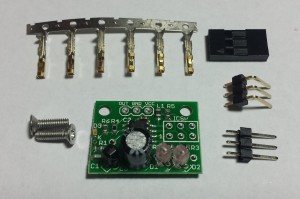
Mini IR height sensor kit version 1.1
A differential modulated IR height sensor. The sensor detects the target height by looking for the reflected light from two separate LEDs to be equal. The two LEDs are positioned such that they reflect light into the sensor at slightly different heights. This allows the sensor to be used most any bed surfaces.
- A high degree of immunity from sunlight, incandescent artificial light, and other background sources of IR.
- Unlike capacitive and inductive sensors, the sensor measures the height to the top surface of a glass bed, not the distance to a backing plate.
- A red LED indicates when the head is at or below target height.
-
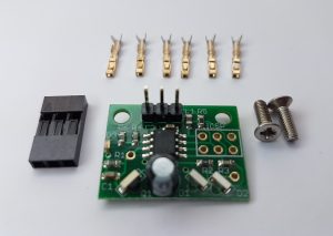
Mini IR height sensor kit version 1.2
Small size, ideal for use where space is restricted, such as under the effector of a delta printer. The current (version 1.1) board is just 24mm wide and 18mm high, small enough to fit below the heatsink of a genuine E3Dv6 hot end.
- Automatic selection of a 4-level analog output for printer electronics that support it (e.g Duet), or a digital output for other printer electronics.
How to get it: For individual sensors and small quantities, please order from duet3d.com (UK) or from a Duet3d genuine reseller. If you wish to purchase 20 or more sensors then you can enquire about direct shipment from me via my Escher3D site.
Specification
- Power: 5V or 3.3V
- Maximum current draw: 20mA @ 5V, or 12mA @ 3.3V
- Size: 18mm high x 24mm wide x 10mm deep
- Weight: 2g (board and 3-way header, excluding socket)
- Trigger height to 3mm glass target on top of black paper: between 2.5mm and 3.5mm
- Reproducibility of repeated probing at same spot: approx. 0.01mm
Mounting the board
The board needs to be mounted with the two fixing holes at the top, and the bottom edge of the board (where the infrared components are mounted) facing the bed and at right angles to it. The sensing area is approximately in the middle of the bottom edge of the board, below the cylindrical capacitor. In order to minimise the effect of any tilt of the hot end as it moves in the XY plane, this area should be as close to the nozzle as reasonably possible, without being so close that the board or the components on it get hot. Mounting it with the back facing the nozzle is recommended, because it reduces the chance of the optical components getting contaminated by extruded filament, and shields the optical components from the heat of the nozzle.
The bottom edge of the board should be no more than 2mm higher than the tip of the nozzle, to ensure that it will trigger before the nozzle touches the bed. To avoid the risk of the board fouling on the print, we suggest that the bottom edge is at least 1mm higher than the tip of the nozzle. So aim for 1.5mm.
To connect the board to your printer electronics, if you have the version 1.1 board then you need to solder either the supplied 3-pin straight header or the 3-pin right angle header to the board – or you can solder wires directly to the board if you wish. The version 1.2 board comes with a 3-pin straight header already fitted. Then use the black 3-pin shell and three of the crimp pins to connect your wires to the header. The remaining three crimp pins I supply are spares.
I provide two M2.5 x 8mm screws for fixing the board. Here are some designs for printable parts to mount version 1.1 and 1.2 sensors. Some of these are designed to secure the hot end or to support fans as well.
- For E3Dv6 hot end: here, here and here
- For E3D Chimera hot end: here
- For J-head hot end: here
- For Printrbot Plus: here
- For the RepRapPro Ormerod: see this thread
- For the JGAurora A5: here
For the older version 1.0 boards I have published a design for a J-head hot end fan duct with a mount for the sensor board here and a design for the E3D v6 hot end here.
Very important! Check that there is no possibility of the board shorting against anything (e.g. the printer frame or the nozzle heating block), even if the head moves outside the normal printing range. Note that the heater block on E3Dv6 and similar hot ends is liable to rotate about the heat break! If the back of the sensor is close to the heater block, you should trim any protruding wire stubs and header pins on the back of the board, and put at least two layers of Kapton tape or alternative high-temperature electrical insulation on the back of the board. It is also a good idea to fit a silicone sock over the heater block, because this will provide additional electrical and thermal insulation. E3D now includes silicone socks with their hot ends, and they can supply socks to retrofit to earlier hot ends that were supplied without them.
Note for delta printer owners: It is important that the effector does not change its tilt relative to the horizontal as it moves in the XY plane. Otherwise, the height difference between the tip of the nozzle and the bottom of the sensor board will vary with XY position, giving rise to calibration errors when you use the sensor to auto-calibrate your printer. If you are using Duet electronics then you can compensate for effector tilt in the bed.g file, but it is better to avoid it in the first place.
Bed surface
For best results, the sensor needs to sense the reflection from the top surface of the bed. There is a potential problem when the sensor is used with a transparent bed material that reflects infrared light weakly and there is a surface below the transparent material that reflects IR much more strongly. Here is a guide to using the sensor with different print surfaces:
- Glass (with or without coatings such as hairspray, PVA or Kapton tape): works as-is if placed directly on a PCB bed heater or other surface that does not reflect strongly. If there is an aluminium heat spreader or bed plate underneath the glass, then either paint the aluminium surface matt black (see below), or put a sheet of matt black paper between the glass and the aluminium. Coatings on the glass affect the trigger height slightly.
- PEI: this is highly transparent to IR. Paint the underside matt black (see below) before using adhesive sheet to attach it to the bed plate. Changes to the surface finish affect the trigger height slightly. We have a report that as an alternative to painting the underside black you can sand the top surface with very fine grit sandpaper until it has a dull matt appearance, but we have not confirmed this.
- BuildTak: the dark grey variant works well with the sensor. I have not tested the white variant, but it should work too.
- PrintBite: early samples were found to be opaque to IR, but more recent samples are transparent to IR. This means that it needs to be painted black on the underside in order to work well with the IR sensor. However, this is not practical if the PrintBite sheet has the adhesive already attached.
- Anodised aluminium, with or without a thin PEI coating: suitable if the finish is matt or semi-matt
- Bright aluminium: not suitable
- Mirror: not suitable
If you need to paint the top of an aluminium heat spreader or the underside of a PEI sheet matt black, then I recommend using spray-on barbecue & stove paint. It needs to be cured at an elevated temperature to harden. I have found 2 hours at 170C in a domestic electric fan oven works well. Caution: the temperature in a domestic oven without a fan will vary greatly in different parts of the oven.
Connecting the board
Looking at the board from the component side, with the mounting holes at the top and the cylindrical capacitor at the bottom, the pads for the 3-pin connector are near the top. These pads are labelled from left to right on the front of the board as follows:
- OUT: this is the output from the board to the printer electronics.
- GND: this must be connected to signal ground on your printer electronics.
- VCC: this must be connected to the +3.3V rail of your 3.3V printer electronics, or the +5V rail if you have 5V printer electronics.
There are also pads for a 6-pin connector, on the right of the board looking at it from the component side. Ignore those pads – they are used for programming only.
Connecting to Duet electronics
![Duet0.6-brd_0.78[1]](https://miscsolutions.files.wordpress.com/2015/05/duet0-6-brd_0-781.png) Duet 0.6 electronics: wire the sensor to the Duet as shown for PROXIMITY SENSOR in this diagram (click on it for a larger version), where the blue wire is connected to OUT, the black wire is connected to GND, and the red wire is connected to VCC.
Duet 0.6 electronics: wire the sensor to the Duet as shown for PROXIMITY SENSOR in this diagram (click on it for a larger version), where the blue wire is connected to OUT, the black wire is connected to GND, and the red wire is connected to VCC.
Duet 0.8.5 and Duet WiFi electronics: wire the sensor to the 4-pin PROBE connector. Connect sensor GND and VCC pins to Duet GND and 3V3 pins respectively. The OUT pin of the sensor should be connected to the AD12 or IN pin on the probe connector. Leave the AD14 or PC10 or MOD pin on the probe connector unconnected.
Duet Shield: connect the board to the 4-pin proximity sensor connector on the shield. Connect OUT, GND and VCC on the board to pins S, G and + respectively on the 4-pin connector. Leave the T pin on the 4-pin connector unconnected.
Duet 3 electronics: connect the sensor to the +3.3V, IN and GND pins of one of the IO connectors.
Connecting to RADDS electronics
If you are using ArduinoDue/RADDS electronics running RepRapFirmware, then you can connect the sensor in analog mode as for the Duet. Connect the sensor to the AUX ADC connector on the RADDS (Gnd to GND, Vcc to 3.3V, and Out to ADC). Then test and commission the board as for Duet electronics.
If you are not running RepRapFirmware, then use the instructions below for other electronics.
Connecting to Smoothieboard electronics
The Smoothieboard uses low value (1K) pullup resistors in its endstop inputs. This is too low for the sensor output to drive, because the sensor output series resistors are chosen to protect the sensor in the event of incorrect connection.
Here are some workarounds:
- Connect the sensor output to a GPIO pin on the Smoothieboard instead of to an endstop input.Use the option “zprobe.probe_pin” in the configuration file to tell Smoothieware which pin it is connected to.
- Add a pulldown resistor from the sensor output to ground (it has been reported that 470 ohms works, but 1K does not).
- Replace the 3K resistor R4 on the sensor board by a lower value (e.g. 220 ohms), or bypass resistor R4 completely. Be extra careful to connect the sensor to your electronics correctly, because R4 protects the sensor from damage if you reverse the connector.
- Increase the value of the pullup resistor on the Smoothieboard to 6.8K or 10K (for the Z_MIN endstop input on a genuine Smoothieboard V1, it’s R100 that you need to change).
Connecting to other electronics
If you are not using Duet electronics, then it probably expects an active-high digital input, for example to the Z low endstop input on a RAMPS board. In this case, connect the three wires from the sensor board to the corresponding wires on the electronics board, as if it were an optical endstop. The Vcc, Gnd and Out pins of the sensor must be connected to the +, – and S pins respectively of the RAMPS endstop connector as shown here. Make sure that the pullup resistor for this input is enabled. When the sensor board detects the pullup resistor four seconds after power up, it sets the output to digital mode.
Warning: the sensor is fairly tolerant to mis-wiring, including having the 3-pin connector reversed. However, if you apply power with the Vcc and Gnd connections swapped over, you will destroy the microcontroller.
Note for Arduino Due users: Boards shipped prior to 5 August 2015 may not recognise the high-value pullup resistor in the Arduino Due, in which case the LED will flash four times at startup instead of twice. A fix is to add an external pullup resistor between the sensor output and +3.3V. Any value between 10K and 47K should suffice.
Testing and commissioning the board
Testing with Duet 2 and older electronics
In your config.g file, use probe type P1 in your M558 command and trigger threshold P500 in your G31 command.
Start with the hot end and sensor some distance above the bed. Power up the Duet using USB power only. About 4 seconds after power is applied, the LED on the sensor should flash four times, indicating that the board has started in analog output mode. If it does not flash, check the power connections to the board.
Connect to the Duet from a PC using the web interface. On the Control page you can see a continuous readout of the Z probe reading.
Send M558 P1 to the Duet, then send G31 P500 Z1.0.
Move a suitable target (e.g. white paper or glass) up underneath the sensor. Check that you get the following readings:
- With the sensor a long way above any surface, the reading should be close to zero.
- With the sensor close to a surface but slightly further away than the trigger height, the reading should be about 465.
- With the sensor slightly closer to a surface, the reading should be about 535 and the red LED on the sensor board should illuminate.
- If you place a surface right up against the sensor board, then the reading may drop to near zero again. This is normal.
- If you see a reading of around 1000, or if the LED flashes rapidly, this means that there is too much ambient IR for the sensor to function correctly. This normally happens only when direct bright sunlight is reflected from the bed into the sensor, or when you place a highly reflective surface below the sensor such as aluminium foil.
If you get the expected readings, then you can apply 12V power and continue with commissioning. If not, check your wiring.
With 12V power applied, send M558 P1 followed by G31 P500 Z1.0 to the Duet again. Note: if your printer does not use the Z probe to home any axes, you also need to add parameters X0 Z0 to the M558 P1 command.
To calibrate the sensor for Z homing and bed probing, home X and Y, then position the head over the centre of the bed. With the nozzle at operating temperature, lower the head so that it is just touching the bed or just gripping a sheet of paper, then send G92 Z0 to define that position as Z=0. Raise the head 5mm and remove the paper. Then send command G30 S-1 to probe the bed at that point without adjusting the Z height setting. Read off the Z height in the “Head Position” box in Duet Web Control, or from the Z coordinate shown on the Control page of PanelDue, or send M114 to retrieve the head position if using a USB host program on a PC. It should be in the range 0.5 to 2.5mm. Use that value for the Z parameter in your G31 command in config.g. Please note:
- Always use a P value of 500. When the probe is triggered, the Z probe reading will be about 535. When it is slightly higher than the trigger height, the reading will be about 465. With a P value of 500, when the Duet sees the reading of about 465, it knows it is getting close to target height and it will slow down the Z motor.
- If you are using my (dc42) fork of RepRapFirmware, then the G31 command in config.g must come after the M558 P1 command. This is because the firmware supports different G31 values for different sensor types.
- After turning your printer on, do not perform any operation that uses the sensor (e.g. X homing on some printers) for 5 seconds, until after the LED has done its 4 flashes.
Testing with Duet 3 electronics
In your config.g file, use probe type P8 in your M558 command and trigger threshold P50 in your G31 command.
Start with the hot end and sensor some distance above the bed. Power up the Duet using either USB or VIN power. About 4 seconds after power is applied, the LED on the sensor should flash twice, indicating that the board has started in digital output mode. If it does not flash, check the power connections to the board.
Connect to the Duet from a PC using the web interface. On the Control page you can see a continuous readout of the Z probe reading.
Send M558 P8 to the Duet, then send G31 P50 Z1.0 (not needed if you already have those commands in config.g).
Move a suitable target (e.g. white paper or glass) up underneath the sensor. Check that you get the following readings:
- With the sensor a long way above any surface, the reading should be close to zero.
- With the sensor close to a surface at the trigger height, the reading should be about 1000.
- If you place a surface right up against the sensor board, then the reading may drop to near zero again. This is normal.
- If the LED flashes rapidly, this means that there is too much ambient IR for the sensor to function correctly. This normally happens only when direct bright sunlight is reflected from the bed into the sensor, or when you place a highly reflective surface below the sensor such as aluminium foil.
Testing with other electronics
I recommend you test the board initially with 5V power only applied (e.g. via the USB connector) if your electronics supports that.
About four seconds after power is applied, the LED on the sensor board should flash twice. This indicates that the sensor has started up in digital output mode. If it flashes four times, check that the output is connected to a suitable input on your printer electronics, and that your firmware is configured to activate the pullup resistor on that pin. If is does not flash at all, check the power connections to the sensor board.
Move a suitable target (e.g. white paper or glass) up underneath the sensor. Check the following:
- With the sensor a long way above any surface, the LED on the sensor should be off, and your printer firmware should indicate that the sensor is not triggered.
- With the sensor closer to a surface than the trigger height (which is approximately 2.75mm measured from the bottom of the sensor board to the bed), the LED should illuminate and your printer firmware should indicate that the sensor is triggered.
- If you place a surface right up against the sensor board, then the LED may turn off again and the status will change to not triggered. This is normal.
- If the LED flashes rapidly, this means that the phototransistor is saturated and the sensor is unable to determine a trigger height. Make sure you do not have strong sunlight reflecting off the target into the sensor, and do not use mirror or bright aluminium as the target. Note: sensors shipped before approx. February 2016 do not flash rapidly when the phototransistor is saturated, instead they produce an output and illuminate the LED as if triggered.
Now use the M119 command to check that the printer recognises that the sensor is triggered when the LED is lit, and not otherwise.
To calibrate the sensor for bed probing, apply 12V power to your printer, home X and Y, then position the head over the centre of the bed. With the nozzle at operating temperature, lower the head so that it is just touching the bed or just gripping a sheet of paper. Send G92 Z0 to define that position as Z=0. Remove the paper and raise the head in small steps until the LED illuminates, and continue raising the head until it goes out again. Now lower the head in 0.05mm or smaller steps until the LED illuminates again. Read off the Z height (e.g. by sending command M114 to your printer) and use that value as the Z probe trigger height in your firmware configuration.
Note: after turning your printer on, do not perform any operation that uses the sensor for 5 seconds, until the LED has done its 2 flashes.
Troubleshooting
LED illuminates (more dimly than normal) as soon as the board is connected. This usually means that you have plugged the 3-pin connector the wrong way round on the board, thereby transposing the Vcc and Out connections. Turn the power off and check your wiring.
LED turns on/off to indicate triggering, but the printer firmware does not recognise whether or not it is triggered. Check that you are getting the correct number of flashes from the LED after power up (4 if you are using Duet electronics or RADDS electronics running RepRapFirmware, 2 for other electronics). If you are getting 4 flashes but expecting 2, then either the sensor output pin is not connected to your electronics correctly, or the pullup resistor is not enabled in your printer firmware, or the pullup resistor has too high a value. If you are getting 2 flashes but the firmware always indicates that the sensor is triggered even when it is not, then the value of the pullup resistor may be too low – see the note for Smoothieboard users above.
Trigger height relative to nozzle varies with XY position. This may mean that there is a large variation in the surface of your print bed, or (if it is a glass bed) in the reflectivity of the surface underneath the glass. Check that the bed surface is the same everywhere you are probing. Another common cause is that the print head is tilting slightly by an amount that depends on XY position (this is common on delta printers). Mounting the sensor close to the nozzle will reduce the effect of any such tilt.
If you cannot eliminate the variation of trigger height with XY position, then if you are using Duet electronics running my fork of RepRapFirmware version 1.09e or later, you can compensate for differences in trigger height using the H parameter on the G30 commands in the bed.g file.
Trigger height too low. This usually means that you have mounted the board too high. The bottom edge of the board should be between 1mm and 2mm higher than the tip of the nozzle. This should give you a trigger height between 0.5mm and 1.5mm. Another possibility is that you are using a glass or PEI bed and the surface underneath the glass is reflective – you should use a black surface underneath the glass or PEI.
Modifications
Modification of the sensor is at your own risk. You can find the schematic here and the firmware source code here. Warning: This product has been designed so that the levels of infrared radiation it emits are safe in normal use . If you modify the hardware and/or firmware, you could cause the infrared LEDs to produce intense invisible light that may be hazardous to the eye when viewed at close range or with a magnification device.
 The trigger height is checked before shipment to be between 2.5 and 3.5mm, measured between the bottom edge of the board and a target of 3mm glass on top of a dark surface. On version 1.0 and 1.1 boards (but not version 1.2 boards, which use SMD optical components) it can be increased a little by mechanically adjusting the angle of the outer LED. Grip the LED by the sides (never by the front, where the lens is) with long nose pliers, then move the pliers so as to rotate the LED slightly anticlockwise as seen from above from its 45 degree position. Only a tiny change in angle is required. Do this at your own risk! Damage to the LEDs is not covered by the warranty. Adjusting the LED position in this way will increase the sensitivity to differences in the bed surface. It will also decrease the overall sensitivity, so it may no longer work with dark surfaces such as BuildTak.
Video
Finally, here is a video showing the board used to perform auto-calibration of a delta printer using Duet electronics. See here for more information on how I configured this. Happy 3D printing!
Appendix: Board dimensions and mounting holes for version 1.1 and 1.2 boards
If the bottom left corner of the board is position (0, 0) then other points on the board are at the following (X, Y) coordinates, in mm:
Top right corner (24.0, 17.62)
Mounting hole centres (2.70, 14.92) and (21.11, 14.92)
Mounting hole diameter 2.8
Last updated 2020-10-28.

Pingback: Building a large delta 3D printer | David Crocker's Solutions blog
So, where can I buy one?
The first batch sold out, but I have just ordered the PCBs for another batch. So I should have more for sale around 22 June. Send me a PM via the reprap.org forums if you wish to pre-order one. My forum name is dc42.
Hi David,
Do you have these in stock again? How much are they?
I expect to have stock again by the end of July. See this thread: http://forums.reprap.org/read.php?94,519697.
Hi David.
I got curious with the Hotend Fan connection indicated in your diagram.
How do you use it? Is there any feature in the firmware for it?
Thanks in advance.
Hi Luis, that diagram is from the RepRapPro Ormerod wiring instructions. The hot end fan is wired direct to the input power, so it runs all the time. I make a separate hot end board for the Ormerod, which includes the IR sensor and also provides thermostatic control of the hot end fan, so that it is turned off when the hot end is below 40C.
Thanks for your reply.
This is exactly what I’am looking for: not having the fan on all the time, only when the temperature is below a threshold. Repetier firmware has that feature, but as I’m migrating to Duet, I’m looking on how to achieve the same feature.
As I already purchased your IT sensor without the fan control, any suggestions?
My current option is to modify the firmware to control a PWM pin and attach an external mosfet to drive the fan (as I do currently with RAMPS).
You don’t need to use a PWM pin. The hot end fan should be run at full speed all the time that the hot end is above about 40C.That’s why it is normally wired direct to the power supply. The Duet 0.6 already has a PWM output pin, but that is normally used for a print cooling fan, which is not the same thing. You could use any spare output pin on the expansion connector to drive an on/off mosfet if you want to turn the hot end cooling fan off when the nozzle is cold. The new Duet 0.8.5 has connectors for two separate PWM fans, so you could have both a print cooling fan and a thermostatically-controlled hot end fan without needing an external mosfet.
I’m going with a 0.6 duet (budget constraints) and an output pin connected to a external mosfet.
Is there a feature already built in in firmware for a thermostatically-controlled fan?
Not yet, although I plan to add one for a future derivative of the Duet.
So what exactly is the Mini height sensor board using some times it seems as if you are saying it is digital and then you will it is analog.
Is it just using a ON/OFF at a certain height or is it really a distance sensor (using ADC)?
It is a distance sensor, optimised to give repeatable results at a particular height (the trigger height). Depending on what printer electronics it is connected to, it produces either a digital output, or a 4-level analog output.
Hi David,
I’d like to replace my z-probe with Your sensor board.
Do You still sell it?
Another question:in the chapter “Testing with other electronics” You’ve wrote:”Now lower the head in 0.05mm steps until the LED illiminates again”.I think this is impossible since I use shield with pronterface and the minimum movement available is 0.1 mm (think3dprint3d mini kossel V2).
Thanks in advance.
Yes, I still sell it. See the “How to get it” paragraph near the start of this page.
Pronterface allows you to define your own buttons that send specific gcodes. So you can define a “Down 0.05mm” button that sends G91, G1 Z-0.05 and G90 in that order. Or use 0.1mm increments instead if you are satisfied with 0.1mm Z-setting accuracy.
I have added your IR Z probe sensor board to my Kossel Mini Release one after adding Duet electronics. I get 1 instead of zero on the web interface when the head is at home.? The IR probe shows 540 when activated, ie led lights. In the detailed instructions I should get zero when the probe is far from the bed.
That’s OK and quite normal, and it won’t affect the performance.
Hi David, I’m building a Kossel Mini using your IR probe. I am commissioning at the moment but I am not getting any response from the IR probe. On power up the LED flashes 4 times, but the Z-probe reading on the web interface is always 0 even if I position glass right underneath the probe. Any thouhgts? Thanks.
If you move a piece of white paper up underneath the sensor, does the LED turn on? If yes, the problem is likely to be that you have a highly-reflecting surface underneath your glass that is confusing the sensor. If no, look at the two IR LEDs through a mobile phone camera to check they are both illuminated. If they are not, contact me for a replacement via the email address on the piece of paper I shipped with the sensor, or contact Filastruder if you purchased it from them.
Hi David,
I am looking at fitting this to a MK8 Extruder and wondered if there are any examples of mounting on this extruder. I have a couple of other questions, is it NC or NO and how does it perform with blue tape as the print surface?
Sorry, I don’t know the Mk8 extruder. When used in digital output mode, the sensor outputs a high level when triggered, low when not triggered, so similar to a NC switch. I haven’t used it on blue tape but I don’t foresee any problems. It may be best to avoid probing over joins in the tape in case the join slightly affects the trigger height.
Thanks for the reply. I am using it with RAMPS and notice if I plug the USB in before the main RAMPS power the probe is detected as analogue (4 blinks). It still appears to work OK so what is the difference between analogue and digital modes?
Interesting, I did my testing with Arduino/RAMPS powered form USB and it started up in digital mode every time. It does depend on how long the Arduino takes to initialize itself – the sensor firmware allows it 4 seconds. In digital mode, with a 5V supply the output will go from 0V to 5V when triggered. In analog mode, it will go from 0V to 2.27V when almost triggered, then to 2.73V when triggered; and if the sensor saturates (which normally happens only above a shiny aluminium surface) it will go up to 5V.
Great project, thank you very much for the effort and for making the fimware and schematics available online.
I designed a PCB for through hole parts and realized, that the electrolytic condesator is placed between the leds and the photo transistor for a reason;)
R5 has a value of 3k6 Ohm on your pictured pcb, is that an earlier version?
The schematic is out of date. There have been several component and firmware changes since I published them.
Has this been tried on a PEI covered glass bed?
Yes, but you need to paint the underside of the PEI black before you glue it to the glass. See https://miscsolutions.wordpress.com/2015/11/30/print-bed-surface-roundup/.
Hi David,
I’ve purchased a board but I’m having some trouble getting it connected to my printer. I’m using a GT2560 with Marlin firmware. My issue is that the endstops only require 2 wires because they’re just digital endstops but your board has 3 wires. I’m not quite sure where to connect the OUT and VCC on my board.
Here is a picture of the board:
Thank you!
Hi, sadly the GT2560 provides 2-pin endstop connectors instead of the usual 3-pin. If you examine the PCB traces or use a multimeter, you should find that one of the pins on that 2-pin connector is connected to ground. Connect the GND pin of the sensor to that one, and connect the OUT pin to the other. For the Vcc pin on the sensor, you will need to solder a wire to the pad labelled “5V” close top one of the corners of the atmega2560 chip, because the board doesn’t make 5V available at a more convenient point.
Would IR reflect off wood and sheet goods, e.g. MDF and plywood. I’m seeking a probe for my small CNC router, Shapeoko 3,
Yes, it should work OK on wood sheets. However, the trigger might might vary slightly depending on surface finish.
Which is the sensor repetibility?
I mean if you have 10 probing on the same point, which is the max difference in Z?
Regards
I just tested that again. On my Ormerod, after probing 10 times the difference between the highest and lowest trigger heights was 63 steps @ 4000 steps/mm = 0.016mm. On my delta, it’s 1 step @ 160 steps/mm = 0.00625mm. The Ormerod tests were done with the hot end at 190C, the Kossel tests were done with the hot end cold.
Repeatability has consistently been better than 3um on my TazMega against glass surfaces. Since this is close to the machine’s theoretical microstepping precision (2.5um), I presume optical repeatability is considerably better.
Also, davidcrocker, you might find this custom heated bed + glass + paint + adhesive + PEI setup interesting. Paint is used to confine worst-case subsurface optical return distance.
https://forum.lulzbot.com/viewtopic.php?f=16&t=4189
Thanks for your comments! I recommend painting the underside of the PEI instead of the bed, because otherwise the adhesive used to attach the PEI to the bed may reflect IR in variable proportions. This is mentioned in the current fitting instructions.
Optically, that would likely be an improvement, yes. One reason for painting the glass was the thin sheets of PEI offered by AlephObjects/LulzBot already include adhesive backing. In fact, results were already usable even without paint, offset by few “bumps”. Needing to replace the PEI sheets on two beds was the motivation for attempting to improve performance in the process. Also nifty that you already recommended high-temperature paint.
By the way, thanks for developing these *awesome* optical probes. Extremely accurate, versatile, and low-cost.
Pingback: D-Bot differential IR Z-probe bracket - 3d Models Aggregator
Pingback: Zprobe Questions – 3DPrintFeed
Pingback: Building a Large Kossel Delta Printer – pt. 3: Electronics and Wiring
Pingback: JGAurora A5 Infrared Sensor | Savvas Papasavva
Pingback: Using a IR Probe on a BigTreeTech SKR 1.4 Board – The Musings of Toni Nguyen
Pingback: 热床常用调平传感器的选择与优缺点 - VORON China
Pingback: HyperCube Mini IR Probe Mount 3D print model – BlingOrbit