
In my previous entry I described my large Kossel-derivative delta printer. Since building it, I have upgraded it in a number of ways, which I will now describe.
Power supply output grounding
 While taking some measurements on my machine, I discovered that the negative side of the output of the 12V LED power supply I am using was not connected to ground inside the power supply as I expected. This presents a safety hazard. So I added an additional wire from ground to the spare negative output terminal of the power supply.
E3Dv6 hot end
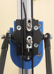
My J-head hot end was working very well, until a metal tooth from one of the Bowden tube pneumatic connectors broke off and got carries into the hot end. I managed to remove the tooth, but it seems to have damaged either the PTFE liner or the metal barrel, because after that the hot end kept clogging. So I decided it was time to try a genuine E3Dv6 hot end. The diameter of the end of the top of the barrel on the E3D was the same as for the J-head, so I did not need to modify the effector.
 The E3D kit comes with a 30mm fan and a fan duct that clips on the heatsink. However, I needed to mount the IR sensor as well, so I chose to adapt my variant of the J-head fan duct for the E3D, which uses a 40mm x 10mm fan instead. My design for the original version 1.0 IR sensor is here and my design for the version 1.1 sensor is here.
The E3D hot end required a change to the config.g file to account for the different thermistor. The correct B value for the thermistor needs to be entered into the M305 P1 command. E3D says to use a B value of 4267, however from looking at the published resistance vs. temperature data for the thermistor, I believe a value of 4388 will provide more accurate readings at PLA and ABS extrusion temperatures.
The print quality with the E3Dv6 is generally similar to the quality I experienced with the J-head, except that with the e-Sun PLA filaments that I mostly use, the E3D leaves small blobs on the print. I believe the blobs are left where the filament was retracted; so it may be that I will be able to eliminate them by tuning the retraction setting. The E3D Lite permits greater retraction lengths than the all-metal E3Dv6 does, so it may be a better option for machines with long Bowden tubes such as this one.
One thing I particularly like about the E3Dv6 is the plastic collar that holds the Bowden tube. This works like a pneumatic connector in that you push it down to release the tube. However, unlike the pneumatic connector, it doesn’t seem to wear out, neither does it wear the tube.
Verdict: the E3Dv6 is well-made and lightweight enough for a delta. My main reservation is the recommended limit of 2mm retraction, which seems very little for a Bowden extruder. I will be happy with it if I can eliminate the small blobs.
Update: I solved the problem of small blobs by configuring 8mm retraction at 100mm/sec.
0.9 degree/step tower motors
My printer uses 20-tooth pulleys and a 2mm pitch belt. This means that when using standard 1.8 degree stepper motors and 16x microstepping, there are 80 microsteps/mm, giving a theoretical vertical resolution of 12.5um. However, not all microsteps are the same size, and the torque provided when moving from one microstep to the next is low. So the actual vertical resolution will be somewhat less.
Changing to higher microstepping drivers won’t help improve the resolution much because the torque provided to move from one 1/32 microstep to the next is even lower. However, 0.9 degree/step motors now cost only a little more than standard 1.8 degree/step motors, and provide almost as much torque between steps even though the step size is half as much. So switching to 0.9 degree/step motors should provide double the resolution, if the motor resolution is not swamped by backlash or other mechanical factors.
I didn’t have any evidence that the resolution provided by my 1.8 degree/step motors was inadequate; but I haven’t tried printing at layer heights below 0.2mm yet. Nevertheless, an increase in vertical resolution would appear to be useful, especially if I want to print at 0.1mm layer height. Hence my decision to upgrade to 0.9 degree/step motors for the towers.
The original motors were 17HS19-1684S, which are 48mm long Nema 17 motors rated at 1.68A with a holding torque of 0.45Nm. The 0.9 degree/step motors I chose were type JK42HM48-1684 sourced from Etang Electronics via eBay UK. These are also 48mm long motors, rated at 1.68A and with a holding torque of 0.44Nm. I subsequently discovered type 17HM19-1684S, which is the 0.9 degree/step variant of the original motors, with holding torque also 0.44Nm, available here. Shorter motors such as the JK42HM40-1684 or even the JK42HM34-1334 would probably be entirely adequate if you are not too fussy about maximum acceleration.
The motors from Etang Electronics did not have flats on their shafts. Although flats are not essential for securing the pulley, I ground shallow flats on the last 10mm of the shafts anyway. They come with flying leads instead of the JST connectors on the original motors, but too short to reach the Duet, so I spliced them to my original motor leads.
 After that, it was a case of making appropriate changes to the config.g file. I doubled the steps/mm in the M92 command from 80 to 160. I soon discovered that the previous maximum speed of 20000 mm/min (333 mm/sec) was not achievable, so I halved the maximum speeds in the M203 command to 10000 mm/min. Increasing the maximum speed will require an increase in supply voltage to 24V and possibly some firmware improvements.
 Do the 0.9 degree.step motors make any difference? Yes, but not much. I printed a 50mm spiral vase test cube before (upper image) and after changing the motors (low image). There is a more noticeable moire pattern with the 1.8 degree/step motors. Under magnification, I could see that the layer alignment was also more consistent using the 0.9 degree/step motors.
Verdict: upgrading an existing printer from 1.8 to 0.9 degree/step motors is probably not worth it for the majority of users. On the other hand, if you are buying parts to make a new delta printer, the additional cost of 0.9 degree/step motors is small and worth paying if you are not on a very tight budget. But I suggest going for a 24V power supply at the same time – which means you also need a 24V heater for the hot end, and a 24V hot end fan (and print cooling fan if you have one).
Extruder design and motor
The original Mini Kossel extruder drive wasn’t perfect. It used the same 48mm high torque motor as the towers, which combined with its gear ratio of about 5:1 meant that the hobbed insert had too much torque. As a result, if the nozzle became temporarily obstructed (e.g. because of over extrusion), the hobbed insert would grind a crescent into the filament, and traction would be lost. It is better for the extruder motor to skip steps when the nozzle is obstructed, so that filament feeding resumes when the nozzle obstruction is removed.
To achieve this, I reduced the extruder motor current to 500mA. Unfortunately, this led to a different problem. The 48mm long motor also has high inertia, which meant that reducing the torque also reduced the available acceleration, to the point where the Load Filament function on the web interface did not work reliably.
To resolve this, I decided to replace the 48mm motor by a 34mm one. I would achieve the same torque as before by running it closer to its rated current, but the lower inertia would give better acceleration. I chose a JK42HS34-1334 motor.
 Before I had a chance to fit the new motor, the extruder drive jammed and the large gear on the extruder drive lost its grip on the hex head bolt. On trying to dismantle it to fit a new gear, I discovered that I could not re-use the hex head bolt or hobbed insert because of the superglue that I applied (as instructed) to hold them together. So I decided that I wanted a better extruder design, one that could be dismantled and reassembled.
As a temporary measure, I removed one of the extruder drives from my dual-extrusion Ormerod and used that. I printed a bracket to mount it on the 2020 extrusion. The Ormerod extruder uses a 34mm JK42HS34-1334 motor (the same one that I had already chosen) with a gear ratio close to 3:1. I find it reliable, although filament left in the printer overnight tends to break in the curved inlet path. I use the spring-loaded variant by masonstonehenge and a remix of the herringbone gears by iamburney.
I plan to adapt this extruder design to better fit the Kossel.
RobotDigg metal carriages with belt tension adjusters
At the time that I purchased the metal frame corners from RobotDigg, they also sold metal Kossel carriages, however they were designed for continuous loop belts. Now they also sell alternative carriages which include locking teeth for securing the ends of cut-to-length belts, and a belt tension adjustment. I decided to try them.
 Fitting them was straightforward, except that they need different lengths of M3 screws to secure them to the trucks and to attach the rod joints than the printed carriages did. Also, the diagonal rod attachment points are half way up the carriage instead of at the top. This lost me 20mm of print height. However, as I was no longer using the upper triangular frame for belt tension adjustment, I was able to put the top triangle right at the top of the vertical extrusions and put the endstop switch mounts right up against the triangle, which recovered about 7mm of build height.
Verdict: these metal carriages are a delight to use, in particular the belt tension adjustment is more precise.
Coming next: 24V power and electronics under the bed
Locating the electronics on the Z tower made it easy to make wiring changes, such as when changing from the mechanical Z probe to the IR probe. But it looks out-of-place, and it makes the printer harder to transport. I believe there is sufficient space under the bed to accommodate the Duet electronics as well as the PSU, SSR and mains wiring, with safe separation between the electronics and the mains wiring. More details to follow in a future entry in this blog.

“My main reservation is the recommended limit of 2mm retraction”
This is about effective retraction inside the hotend. With a bowden tube you also need to retract out the pressure that’s built up inside the bowden tube.
You were quite right. I’ve increased retraction to 8mm, and the small blobs I was getting are gone.
Pingback: Ormerod and Mini Kossel 3D printer kits compared | David Crocker's Solutions blog
Hey Dave, watching your blog with interest! 🙂
If you’d like I can provide you with the spring loaded extruder in the native Solid Edge file format – If you’ve got access to Solid Edge or Solid Works or suchlike you would be able to make the appropriate changes easily.
Thanks for your offer! Unfortunately I don’t have Solid Edge or Solid Works. All I really need is a version of the extruder with the larger radius inlet, the nut trap for the adjusting screw made smaller so it grips an M3 nut, and with the Ormerod mounting hook at the end removed. I’ve given up on the pneumatic connectors so I am back to using the Brass bowden end and locking tab.
I would love to have these files. I’m building a Delta printer this Winther, and I’m having Access to SolidWorks.
Hi David
I have 3 of these laying around http://www.ebay.co.uk/itm/231657793070?_trksid=p2057872.m2749.l2649&ssPageName=STRK%3AMEBIDX%3AIT
Do you think they will do for a delta printer of the size you have built?
Regards
Jan
No. Those are 12V 0.31A motors and will work poorly even with a 24V supply. Choose motors with a rated current of 1.3 to 1.8A and voltage of about 2.5 to 4V.
I love what you have done to this Kossel of yours. I really wish this whole setup came in a kit as I am dying to make a larger Kossel with better electronics.
Think3DPrint3D has a kit based on my design in beta.
Dave, how high did you set your stepper currents with 24V? What about your M201, M203 and M566 settings? At the moment I have them set to 1000mA and cannot achieve feed rates higher than 10000. When I do ‘G1 Z0 F20000’ from homed position all seems to be OK but when doing G1 Z400 F20000 quite often one of the motors stops moving. With slower feed rates all is OK. Should I be aiming at getting to 20000? How high can I push the stepper currents on Duet 0.8.5 at 24V? The nominal current for my steppers is 1.65A and they are 0.9 degrees/step.
Here is a section from my config.g (I am using 16 teeth pulleys)
M92 X200 Y200 Z200 ; Set axis steps/mm
M906 X1000 Y1000 Z1000 E500 I60 ; Set motor currents (mA) and increase idle current to 60%
M201 X1000 Y1000 Z1000 E1000 ; Accelerations (mm/s^2)
M203 X20000 Y20000 Z20000 E3600 ; Maximum speeds (mm/min)
M566 X1200 Y1200 Z1200 E1200 ; Maximum instant speed changes mm/minute
David,
My Midi (250mm bed; 750x360mm extrusions) version is now virtually finished with more than just a little help from T3P3. J’adore your IR Sensor and firmware – makes life so much simpler. I’m just short of the bed heater as China let me down. So I’m using T3P3 filament without a heated bed. I’m running 24V PSU with the 0.9deg stepper motors you recommended for the X,Y,Z motors but my original motor from my Ormerod 2 for the extruder. My current E setting is calibrated @ 428 and the extruder motor current @ 500mA.
I notice that for small repetitive moves the Ormerod extruder (with spring and helical gears) is knocking an awful lot i.e. Bowden end doing its nut.
Any ideas what needs tweaking to improve matters?
Everything is calibrated.
Thanks
Maurice
Looks like it was a newbie problem setting up an E3DV6 lite. I did not manage to get the Bowden tube far enough down into the heatsink. So the gap was a mess/mass filament that was an obstacle to smooth extrusion. I still think the extruder motor idle current is a bit severe on the gears, but the only way of reducing it and not affecting the X.Y.Z motor idle current is by reducing the extruder Busy current from 500mA. I will try this later. Unless someone comes up with any better ideas?
I’m glad you solved it. I have been told that it is a good idea to taper the end of the Bowden tube (e.g. with a pencil sharpener), because the bottom of the Bowden tub inlet in the E3D hot end is tapered.
The lite version has the Bowden tube butted against the nozzle so tapering may cause problems.
The moire/salmon skin reduction from 1.8 to 0.9 deg motors seems pretty substantial.
Is there anyone who has replicated these results?