
My large delta printer has been working quite well since the last round of upgrades, but two issues have been bugging me. First, although spiral vase prints were excellent with perfect layer registration, some other prints showed a small misalignment between some of the layers. Second, when I measured the trigger height of the IR sensor at each probe point, I found that the trigger height close to the Z tower was about 0.25mm higher than in most other places. I corrected for this using the H parameter for the probe points affected on the corresponding G30 commands in the bed.g file, so it didn’t affect the delta calibration. But it shouldn’t have been necessary.
Identifying the cause
I suspected that the increased trigger height near the Z tower was due to the effector tilt varying. I confirmed this by lowering the nozzle on to the bed until it gripped a piece of paper, then removing the paper and measuring the height of the bottom edge of the IR sensor board above the bed. I repeated this for all the probe points. It confirmed that the difference in trigger height was being caused by the effector tilting about the X axis, which caused the sensor board to drop a little relative to the nozzle when the effector neared the Z tower.
Further investigation revealed a probable cause. About half the Traxxas joints in my printer were tight, but the other half had a small amount of play. Because of this play, I found I could tilt the effector slightly by applying pressure. The Bowden tube in my printer applies a sideways force from the top in the Y direction; but when the effector nears the Z tower which the extruder is attached to, the sideways force changes direction. This was enough to cause the effector to tilt slightly, so as to take up the play on the other side of the loose joints.
First attempt at a solution
I attempted to solve this by using springs to take up the free play. First, I rotated rods end-to-end where necessary so that almost all the loose joints were at the effector end. Next, I put a spring between each pair of rods, close to the effector, and held in place by cable ties.
This modification reduced the difference in trigger height by about half. But I still wasn’t satisfied. I suspected that the free play might also be the cause of the imperfect layer registration.
In search of a better solution
I decided that the joints had to be replaced. One option would have been to buy about double the number of Traxxas joints I needed, assemble them as best I can using the hot/cold method, throw away those that had some free play, and build new rods using the rest. But I decided to try a different type of joint instead.
Many delta printers use ball-and-socket joints, held together using either springs or magnets. I considered changing to magnetic joints, and I may well try them in future. However, this would have required new carriages and a new effector. I particularly like the Robotdigg carriages with the integral belt tension adjusters.
Instead, I decided to make a new set of arm using Igus joints instead of Traxxas, that I hoped would be compatible with the existing carriages and effector. I also decided to support some of the weight of the Bowden tube from the top of the frame, to lessen the sideways force.
Replacing Traxxas joints by Igus: the issues
I expected the Igus joints to be more or less a drop-in replacement for the Traxxas, but things were not that simple:
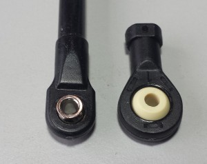
- The Traxxas 5347 joints have a ball with a 3mm hole and a tail that accepts a 4mm thread. The 3mm hole makes them compatible with the Robotdigg metal carriages. A 20mm x M4 set screw can be screwed into the tail, and the other end of the set screw can be epoxied into the end of a length of 6mm o.d. x 4mm i.d carbon fibre tube used for the diagonal rod. Simple. Unfortunately, Igus joints that accept a 3mm screw in the ball also have a tail with a female M3 tail. You could use them with M3 set screws epoxied into 5mm o.d. x 3mm i.d. carbon fibre tube. However, 5mm tube is in my opinion far too flexible for use as the 355mm arms of my delta. To solve this, I connected the tail of each Igus joint to a 20mm long piece of 5mm x 3mm tube, then I epoxied this into the inside of a piece of 7mm o.d. x 5mm i.d. tube. So my rods are now 7mm diameter instead of 6mm, and stiffer as a result.
 The Igus rod ends are much larger than the Traxxas rod ends. When I first attempted to install the rods with Igus joints, I found that the rod ends fouled on the edges of the carriages, the effector, the hot end fan, and each other at the effector end. I attempted to solve the fouling at the effector end by filing down the rod ends and the fan, but failed to deal with it adequately. In the end I gave up using the Robotdigg aluminium effector, and printed a new effector that was 10mm larger in diameter. This might have reduced the potential printable diameter by 10mm by keeping the nozzle 5mm further away from the towers, but in practice it doesn’t because the protruding hot end fan was previously the limiting factor.
 Although the Igus rod ends allow a theoretical 30 degrees of pivot movement, it’s hard to achieve this because whatever screws etc. are in contact with the ball foul the housing. The Traxxas joints avoid this by using a metal ball that extends a little on each side to form stand-offs. I didn’t realise this until after I had assembled the rods. I resolved the issue using tapered spacers, but the joints are right at the ends of their travel at some positions. So I think it best to lengthen the arms a little in order to reduce the range of movement needed at the joints. In the following, I assume you will increase the arm lengths by 20mm. This will of course reduce the build height by the same amount.

Parts needed for the arm upgrade
2 off 7mm x 5mm x 1m pulltruded carbon fibre tube (Easy Composites)
1 off 5mm x 3mm x 1m pulltruded carbon fibre tube (Easy Composites)
12 off Igus KBRM-03 joints (Igus)
12 off M3 x 20mm set screw
24 or 33 off M3 x 5mm o.d. x 4mm long round brass spacers (Spiratronics via eBay UK) – but see text
Epoxy resin (I used Z-poxy 30 minute)
New printed effector with rod end bearing offset increased from 20mm to 25mm
6 off M3 x 20mm cap head screw
6 off M3 x 30mm or 35mm cap head screw (see text)
6 off M3 nyloc nut
About 1m of thin elastic, or a long, weak tension spring
 Assembling the new arms
Start by making a jig to ensure that all the rods are precisely the same length. I slid the heads of two M3 countersunk screws into a piece of 1515 extrusion and secured them each with a washer and nut, to leave two M3 screws protruding spaced 370mm apart.
Next, cut each of the 1m carbon fibre tubes into three lengths of about 333mm. There is a video on the Easy Composites website showing how to cut carbon fibre composites and what precautions to take. The important thing is to wear a dust mask and to vacuum up the dust. You will also need 12 pieces of the 5mm tube, each about 20mm long. These pieces need to fit inside the ends of the 7mm tube. I found they needed to be sanded down to fit – again, wear a mask and vacuum up the dust.
Screw an M3 set screw tightly into each Igus joint. Now epoxy one of the 20mm lengths of 5mm tube on to the protruding part of the set screw, flush with the tail of the joint. Leave for long enough for the epoxy to harden at least partially.
Assemble a rod by smearing epoxy over the 5mm tube attached to one of the joints and slipping it in to one of the 7mm tubes. Repeat for the other end. Fit the rod assembly on the jig so that the joints are held the correct distance apart, and rotate the joints until the two ends are parallel. Leave in a warm place to set firm. Then you can remove the rod assembly and use the jig to make the next one.
 The round brass spacers are needed to keep the bodies of the Igus joints from fouling the carriages, the effector, and the heads of the screws that attach them. Ideally, 4mm o.d. spacers would be used, but the smallest I found were 5mm. So you need to taper one end of each spacer down to about 4mm. I did this by putting the spacer in the chuck of an electric drill and holding a file against the rotating spacer.
After I had completed this upgrade, I found some 4mm o.d x 5mm long M3 spacers. They would not need to be tapered, but you would need to use 35mm screws for securing the arms to the effector instead of 30mm.
 If you followed my original instructions and used a stack of washers to stand the carriage wheels off from the carriage trucks, then you may wish to get another 9 spacers to replace the stacks of washers. Either 4mm or 5mm long spacers would be suitable.
Then it’s just a case of replacing the old effector and rods with the new ones. When fitting the arms, place one spacer on each side of each Igus joint, with the tapered end towards the joint. Do not over-tighten the screws – doing so tightens up the Igus joints, and you want them to move freely.
 The elastic is used to support the weight of the Bowden tube from the top frame, to lessen the torque it applies to the effector. If you intend to use a heated chamber, you may find that a long, weak tension spring can better handle the temperature.
Calibration
The increase in effector size makes the rods slightly more vertical, and if you followed the instructions above then the new rods will be 20mm longer, so the homed height will need to be adjusted. This is easily done by sending M558 H30 to increase the probing height to 30mm, running auto calibration a couple of times, then running M665 and M666 with no parameters, and copying the reported values back into the M665 and M666 commands in config.g.
If you previously measured the Z probe trigger height at each probe point so that you could make corrections for it in the bed.g file using the H parameter on the G30 commands, you will need to measure those heights again.
Results
It took a lot of work to get sufficient movement range from the Igus joints, but now that it is done, there has been a noticeable improvement in layer registration compared to the Traxxas joints.
On the other hand, the increase in Z probe trigger height when the effector was close to the Z tower remained. However, when I replaced the stacks of washers used to stand the wheels off from the carriage trucks by spacers, I discovered that one of the stacks had an extra washer. This caused a slight twist in the carriage, making it impossible for the attached rods to be perfectly parallel. Since installing the spacers, the problem is much reduced. So I intend to devise a way of telling whether the lines between the bearing centres on the three carriages are at exactly 120 degrees to each other, and to correct any inaccuracy using shims under the spacers.
Next time I will discuss different print bed materials I have used.

Can’t wait for u to get a solution to the bearing center and 120 deg alignment. This might help me
Not tempted by linear guides? Very easy swap on a Kossel Mini or similar, and not overly expensive. Even a typical cheap, average quality set should knock any carriage issue on the head, and stiffen your frame to boot!
Dave, one issue I have found with my ‘big’ Kossel based on your design is getting the carriages perfectly centered on the posts. Does your design allow you to tweak the degrees of freedom necessary to get them lined up? The degrees of freedom that can affect accuracy and will require calibration are (that I can think of): centering the carriage on the post; rotation around the axis normal to the carriage; possibly tilt around the vertical axis.
thanks
A small fixed rotation of the carriage about an axis normal to the carriage will cause a corresponding effector tilt but won’t affect the calibration. If the carriages are not quite centred on the posts, that can be calibrated out by adjusting the tower positions. The only fixed rotation that causes a problem is rotation of a carriage about an axis parallel to the towers. That can be adjusted with washers or shims under the wheels.
I’m working on building a larger Delta based on your design. Thanks for everything! I was wondering if I could get a link to a STL version of the end effector? Perhaps it’s on Thingverse? I can’t use the scad info.
Download Open Scad, it’s free. Then select the mounting hole radius you require, press F6 to compile, then File->Export->As STL.
I have Open SCAD, but where are files for KOSSEL parts? I found some I had to redesign because some holes are not centric and effectors do not have system for hooking toothed belt, nor are things useable with my sliding profiles.
Likewise, I am trying to build some ROSTOCK Delta and while I have program for arms lenght for KOSSEL, I have problem determining arms lenght. Workspace diameter should be 60cm and 120cm height. Someone told me endstop switches on downside are not necesary, but I would like to put 3 proximity sensors on central platform, for automatic bed leveling. Also have idea to put 3 extruders that would feed one hot end in center. Is it possible or even done before? Any advise would be greatly appreciated. I am inventor of new Wind Turbines, so I would need even larger 3D printers later. One other problem is that generated GCODE seems to be gargantuan, for 80 cm lenght (printing height) of turbine 473 TERABYTES on HD is required! Please HELP!
The Kossel printed parts I used are in my github repository https://github.com/dc42/kossel. Please ask your other questions on one of the forums, for example https://www.duet3d.com/forum/index.php or https://groups.google.com/forum/#!forum/deltabot.
Do you have any experiences about using magnetic balls instead Traxxas joints? They seem a nice upgrade for the rods, (you can swap effectors easily for multiple applications). But I’m not sure how these would perform vs the Igus joints.
I haven’t tried magnetic joints yet, but I have been given a set of steel balls on screw threads. Now I just need to find someone to turn some conical sockets/magnet holders/rod ends in PTFE for me.
How are you finding your igus rod ends after a few months of printing? I am looking to upgrade my printer with Igus rod ends too. I current have chinese M5 brass rod ends and they chatter horribly because of the loose clearances and weigh a ton!
The Igus rod ends have more friction than the Traxxas, and I think this is why I am no longer getting such good layer registration as before. So I am considering reverting to Traxxas ends, but keeping the increased rod spacing.
That is very interesting. I have used some other Igubal products before so I know what you mean about them being tight. Perhaps I will have to find better metal rod ends instead. At the moment my POS5A rod ends are very free, at least thats one thing they do well.
I’ve build my Delta printer with magnetic balls but after many printings, I’ve decided to use ball bearing because magnetic balls are not strong enough when i print quickly. I just receiving this model:
http://fr.aliexpress.com/item/12pcs-lot-Kossel-Mini-Rostock-Robot-Delta-3D-Printer-Rod-Ends-Self-lubricating-Rod-Ends-Bearings/32255753559.html?detailNewVersion=2
Have you received them yet? Are they PTFE lined? I have a similar rod ends from China, but I could only find ones with bronze liners. They work well but do have a bit of play in them.
Hi, your blog posts are really great and rich in details, I’m currently upgrading my delta to a larger one by changing openbeam and rods,
I’m currently have robotdigg corner and want to use 360mm openbeam 2020, my bearing offsets are standard (22mm for the effector and 19mm for the carriage on mgn rails)
but how did you calculate your rod lenght ? you use 350mm (hole to hole) rod length for 355mm horizontal openbeam.
There are at least two constraints on rod length:
1. Rods should be long enough that when the effector is at the edge of the bed opposite a tower, the rods to the carriage on that tower are at and angle of at least 20 degrees to the horizontal.
2. Rods should be long enough that the joints have enough movement angle. Igus joints have less movement than Traxxas even if you use spacers as I described.
If you make the rods too long, you lose build height and also resolution near the centre.
I currently have MPJet joints, (I do some Rc model, I prefer this brand to traxxas) didn’t make a test to check the max angle yet
Did you use a specific tool to check your rod lenght with the bed size you wanted? I suppose the max angle have to be checked at the edge of the bed between 2 towers
Thanks for your answer, but how did you come to choose 355mm openbeam (instead of 360mm which “seems” more logic) and 350mm (hole to hole) arm length ?
And at which point do you lose a significant resolution in the center ?
Sorry to bother you with these questions but I tried to find calculators to help me but every time these calculator use assumptions that I don’t have like inner triangle. The only relevant input that I have are :
– I’ve got robotdigg metal corner
– I would like to use horizontal 360mm 2020
– I use mgn rails so I know my offset from 2020 vertical toward the center
– I know my offset on my effector.
I chose the dimensions starting from a requirement for 300mm diameter printable area. From that I calculated where the belts needed to be, and from that where the towers needed to be – which led to the 355mm horizontals.
Questions about delta printer design can be asked at https://groups.google.com/forum/#!forum/deltabot or http://forums.reprap.org/list.php?178.