
In my previous post I described the Robotdigg SCARA Arm 3D printer in its original form. This post covers the conversion to Duet Ethernet electronics. It may seem odd to use top-of-the range electronics with budget mechanics, and I am not suggesting that it would make sense for other owners of this printer. In my case it made sense because I needed a test bed for testing and maintaining SCARA support in RepRapFirmware, the firmware that runs on the Duets.
Which Duet?
The Series 2 Duets comprise the Duet WiFi and the Duet Ethernet. These 3D printer controller boards are identical except that one provides WiFi connectivity and the other provides Ethernet. The WiFi would have made more sense for this conversion because the electronics rotates with the printer, making a cable connection a little clumsy, and I don’t have issues with WiFi signal strength or congestion in the 2.4GHz WiFi band. However, as I already have a Duet WiFi-controlled delta printer, and I needed a test bed not only for SCARA support but also to help test new firmware releases for the Duet Ethernet, I chose to use the Duet Ethernet. Exactly the same conversion could be done using a Duet WiFi instead, except that the enclosure would need a cutout to accommodate the WiFi antenna instead of the Ethernet connector.
Enclosure

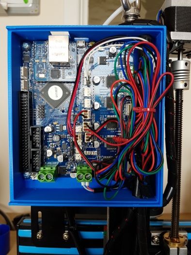
The acrylic electronics enclosure supplied with the SCARA arm printer is about 117mm square internally, which is slightly too small to accommodate a 124mm x 100mm Duet. So I took my previous design for a printable Duet enclosure for the Mini Kossel and adapted it to suit the Duet Ethernet and Robotdigg printer. The enclosure is designed to replace the original black acrylic box attached to the vertical axis. Details on thingiverse.
The original electronics enclosure has a 40mm cooling fan blowing air through it. The Series 2 Duets with their TMC2660 drivers produce very little heat even up to 2A motor current – and the motors in this printer are rated at less than that (1.68A). Therefore the cooling fan is unnecessary, and in the interests of keeping the printer quiet I dispensed with it.
Changing the electronics
The wires connected to the original electronics were not labelled, and it’s not easy to trace them to the motors or homing switches because they are enclosed in black spiral wrap for most of the cable run. There were 4 identical stepper motor cables plugged into the board. However, the sockets they were plugged into were labelled x, y, z0 and e0. Similarly, the three identical homing switch wires were plugged into socket positions labelled XYZ. So as I disconnected the wires, I placed colour coded spots on the connectors and the corresponding motors, assuming that X and Y were connected to the proximal and distal motor and switch respectively. The heater and thermistor wires used different types of cable, so they were readily identifiable. The hot end fan wires had different colours from the rest, green for + and blue for -.
 After removing the original electronics enclosure from the vertical axis of the printer, I removed the power connector and lead from that enclosure and re-installed it in my new one. The power socket is jammed into the hole for it, as in the original enclosure. It seemed secure enough, but I added a little superglue just in case.
Then I installed the new enclosure and electronics on the vertical axis, cut off the old connectors and crimped on the ones supplied with the Duet Ethernet. Most of them were straightforward, however the homing switch wires had very fine copper cores and failed to make good connections the first time I crimped them. In retrospect, it would have been easier to remove the pins from the 2-place Dupont shells and fit them into 3-place Dupont shells instead.
Most of the wires were too long, and I kept the extra length in case of future modifications. But the hot end fan wires were too short and I had to extend them.
I connected all the wires to the connectors on the Duet that corresponded to the original connectors on the old electronics, save for the hot end fan. This fan had originally been connected directly to the power input terminals, so it ran continuously. I connected it to the FAN 1 output of the Duet instead so that I can control it thermostatically.
Testing and configuring
With USB power applied, I checked that the red +5V and green +3.3V LEDs on the Duet were illuminated. Then I tested the homing switches. This is easy on the Duet, thanks to the indicator LEDs. This revealed the bad crimp connections that I already mentioned.
With the homing switches all giving the correct indications on the Duet, I connected to the USB port using Pronterface, connected the Ethernet cable from my router as well, and sent M552 from Pronterface to find out what IP address my router had assigned to the Duet. Typing that IP address in the address bar of Chrome brought up the web interface.
Now it was time to set up the config.g file and homing files. Normally these can be generated by the RepRapFirmware configuration tool, but it doesn’t yet support SCARA printers. So I edited the existing config.g file on the Duet’s SD card in the web interface instead.
I read the Marlin hard-coded settings from the old controller board by sending M502 then M503. The results are here. The Marlin configuration gave the steps/degree as 71.5 for the proximal motor (although before I ran M502 to clear EEPROM it gave 71.4), 80 for the distal motor, and 1650 steps/mm for the Z axis. The value of 71.5 didn’t make sense because it isn’t a rational number that is likely to relate to the ratio of pulley teeth. A combination of measurement and guesswork led me to conclude that the proximal drive used a 15-tooth pulley on the motor driving the large pulley of 120 teeth. At x16 nominal microstepping, this gives a steps/degree value of 200 * 16 * 120/(15 * 360) = 71.1111. The distal joint had two stages of reduction, each one a 20-tooth pulley driving a 60-tooth pulley, hence 9:1 reduction overall. This gives 200 * 16 * 9/360 = 80 steps/degree, which agrees with the value that was configured in Marlin. The X leadscrew pitch appears to be 2mm, giving 200 * 16/2 = 1600 steps/mm, as opposed to the 1650 steps/mm configured in Marlin.
I estimated the proximal and distal arm lengths as best I could. Likewise the arm angles when the homing switches are triggered.
Printing

After the conversion, the first thing I noticed was how quiet the printer was when printing. The noisiest component was the power brick, which produces an annoying buzz when the heater PWM kicks in. Perhaps I should increase the heater PWM frequency to ultrasonic, or else get a new power brick.
After a few firmware bug fixes (I did say that I wanted to use this printer to test the SCARA support!) and tweaks to the config.g and homeall.g file, I had the printer producing a respectable Escher lizard. The jerky movement seen with the original electronics and Marlin firmware is gone, and I was able to increase the maximum speeds from 30mm/sec to 50mm/sec for perimeters and 80mm/sec for infill.
Calibration
The Escher lizards I printed at first wouldn’t tessellate with ones printed on other printers because of dimensional inaccuracy. So it was time to calibrate the printer, to find accurate values of the M669 SCARA parameters.
The steps per degree for each joint can be assumed to be accurate, because this just depends on the ratio of pulley teeth. That leaves 6 parameters that affect how the arms are moved to reach a given XY position: the two arm lengths, the two joint angles at which the homing switches are triggered, and the XY offset of the bed origin. Changing the XY offset just moves the print, and changing the proximal joint homing switch position just rotates the print. So these three do not need to be calibrated, instead they can be adjusted after the other parameters have been calibrated to place the bed origin at an appropriate position and the X axis at an appropriate angle.
That leaves three parameters to be calibrated: proximal arm length, distal arm length, and distal joint angle when the homing switch is triggered. To aid calibration, I set up a macro file called Dab that as its name suggests dabs a spot of filament onto the bed at the current XY position, assuming that the hot end is up to temperature. Here is the contents of that macro file:
G1 E3 F3600  ; prime filament
G1 Z1
G1 E3.5 F300 ; prime and extrude a little filament
G4 P500      ; wait for it to stick
G1 E-3 F3600 ; retract filament
G1 Z10       ; move away from the bed
To perform calibration, I set up a macro that dabs four spots, using two proximal arm positions spaced 60° apart and two distal arm positions spaced 90° apart. To prevent backlash affecting the measurements, I made sure to approach the arm positions from the same direction each time. This is my Calibrate macro:
G28                   ; home
G10 P0 S210           ; set active temperature
T0                    ; select tool
M116                  ; wait until hot
G1 S2 X-3 Y32 F3000   ; approach target arm positions from below
G1 S2 X0 Y35 F300     ; move to target
M98 P/macros/Dab
G1 S2 X-3 Y122 F3000  ; approach next target from below
G1 S2 X0 Y125 F300    ; move to next target
M98 P/macros/Dab
G1 S2 X-63 Y32 F3000  ; approach next target from below
G1 S2 X-60 Y35 F300   ; move to next target
M98 P/macros/Dab
G1 S2 X-63 Y122 F3000 ; approach next target from below
G1 S2 X-60 Y125 F300  ; move to next target
M98 P/macros/Dab
G0 X0 Y100 Z25 F3000  ; move head out of the way
If the spots are labeled 0, 1, 2 and 3 in that order, and the 60° and 90° angle movements were accurate, then by applying some geometry and the cosine rule we find that the distances between those spots should obey the following, where P is the proximal arm length, D is the distal arm length, d01 is the distance between points 0 and 1, and so on:
d012 = d232 = 2*D2
d022 = P2 + D2 + 2*P*D*cos(Θ)
d132 = P2 + D2 - 2*P*D*sin(Θ)
where Θ is the smaller of the two distal angles we commanded – this is nominally 35° in my calibration file, but not accurate due to uncertainty in the homing position. We can rearrange these and solve them to give:
D = (d01 + d23)*sqrt(2)/4
d022 - d132 = 2*sqrt(2)*P*D*sin(Θ + 45°)
d022 + d132 = 2*(P2 + D2 + P*D*sqrt(2)*cos(Θ + 45°))

The distal arm length is given directly by the first equation. The proximal arm length and distal arm angle could be obtained by various ways of solving simultaneous nonlinear equations; but I found it easier just to set up a spreadsheet to calculate the theoretical values, and adjust the input P and Θ values until the calculated values agreed with the measured ones to within 0.1mm. The values came out as P=160.0mm, D=160.2mm, and distal arm angle when homed 157.4°.
After that, I was able to print Escher lizards that tessellated with the ones produced by my two other 3D printers.
The config.g and homeall.g files that I ended up with can be found here here.
Next time: improving the mechanics!
