
In the first post in this series I described how I strengthened the bad T-frame of the printer and added adjustable levelling feet. These improvements made it possible to produce prints. The conversion to Duet electronics described in my second post improved print quality and provided faster print speed. However, the large amount of backlash in the distal arm joint drive remained, along with the lesser but still serious backlash in the proximal joint drive. If I was ever to get good prints from this printer, the backlash in both joints would need to be addressed.
Removing backlash
I had observed that the main cause of the backlash was the belt moving relative to the second small pulley (the one not on the motor) in the distal drive chain, and to a lesser extent the belt moving relative to the small pulley on the proximal drive motor. The teeth of an MXL belt are narrower than the gaps between teeth, therefore MXL pulleys need to have teeth somewhat wider than the gaps between teeth in order for the belt to fit snugly. But it was clear that the MXL pulleys fitted to the printer did not have this tooth profile, hence the belt was able to slip.
The simplest approach would have been to replace the pulleys with ones having the correct tooth profile. However, the listings for MXL pulleys that I found on eBay gave me no confidence that any replacement pulleys I purchased would have a better tooth profile. So I decided to look at replacing all the pulleys and belts with GT2 ones. The GT2 tooth profile has equal tooth width and tooth spacing; furthermore, GT2 pulleys and belts are reported to have less backlash than MXL ones.
Distal drive system
The distal drive system had two 60-tooth pulleys with 8mm bore, one 20-tooth pulley with 8mm bore, and one 20-tooth pulley with 5mm bore. The belts each had 154 teeth, giving a total length of 320mm, and were 10mm. wide. I was able to find similar GT2 pulleys, but only for 6mm wide belts (I would have preferred 9mm). GT2 belts were available in various lengths including 160 teeth (320mm). So initially I did a direct replacement of the 10mm wide MXL pulleys and belts with 6mm wide GT2 parts.
The GT2 pulleys have a slightly smaller diameter than the MXL parts due to the smaller tooth pitch. This meant that I had to move the intermediate shaft and the drive motor along the proximal arm, away from the distal joint. Moving the motor further out from the proximal axis than it was already increased the moment of inertia of the proximal arm. So I replaced the belt connecting the distal joint to the 20-tooth pulley on the intermediate shaft by a shorter belt, 130 teeth (260mm) and repositioned both the intermediate shaft and the motor. At the same time I replaced the 20-tooth motor pulley by a 16-tooth pulley, thereby increasing the distal joint resolution from 80 to 100 steps per degree.
This modification removed the observed backlash in the distal joint completely. There is a small amount of springiness in the distal joint, probably due mainly to belt stretch; but although 9mm belts and the corresponding pulleys would have been preferable (at least for the second belt in the drive chain), I don’t think the springiness is excessive.
Proximal drive system
The proximal drive uses a 15-tooth 5mm bore motor pulley driving a 120-tooth 8mm bore pulley. The bottom of the 120-tooth pulley is partially drilled to a larger diameter to accommodate the M8 nut that holds the Z axis together. It also has four 4mm holes drilled in it to secure it to the base T-frame.
My initial thought was to replace the proximal drive components by GT2 components too. However, I was unable to locate a 120-tooth aluminium GT2 pulley with end flanges and 8mm bore. Searching for alternatives, I came up with three possibilities:
- I found a supplier on eBay offering a 120-tooth/15-tooth HD3 reduction gear and belt set. Because of the increased tooth pitch (3mm), the large pulley diameter would be about 120mm instead of 80mm, so I would have to set the Z axis back by 20mm, losing 20mm build depth at the front.
- I located a manufacture (Chemi-Flex) of urethane MXL belts who make them with a tooth angle of 60° instead of 40°, for reduced backlash. But they don’t keep stocks, and their minimum order is 50 to 100 pieces.
- I located a UK-based supplier (MOTIONCO) of 15-tooth MXL pulleys. The pictures suggested that they had the correct MXL tooth profile. Unfortunately they were not available in 11mm width, so I would have to replace the MXL belt with a 6.25mm wide one at the same time.
I decided to try #3 first, with #1 in reserve. MOTIONCO doesn’t sell a 154-tooth MXL belt, so I ordered 150- and 160-tooth belts, along with a 15-tooth pulley. The combination of the 150-tooth belt (model BMXL150) and the pulley (model PLMXL015AL-05) virtually eliminated the backlash. The tooth profile of the belts were significantly different from the original belts received from Robotdigg, so it is possible that replacing the belt alone would have been sufficient.
Adding a Z probe
The adjustable levelling feet I described in part 1 of this series made it possible to level the printing plane over a sufficient area to do small prints. However, the potential build area of this printer is around 300mm x 200mm with additional width available at the edges with reduced depth. The forces causing the head to sag vary greatly with the XY position of the print head, and the desk that I was printing on (covered with a printing surface of blue tape) was unlikely to be level to the required accuracy over that area. So a Z probe is essential. The requirements in this application were:
- It must have little weight
- It must work well using a target surface of blue tape on MDF
- It must be possible to mount it very close to the nozzle. In most printers, XY offset between the Z probe and the nozzle can be compensated. But in a SCARA printer, the print head rotates, so the XY offsets are not constant. In principle the Z probe offset from the nozzle could be specified as a modified distal joint angle and a modified distal arm length, so that the probe can be moved to the exact spot required; but RepRapFirmware doesn’t implement this yet.
 My own Mini Differential IR Sensor meets these requirements.
To mount the sensor, I printed a new hot end fan duct with extra tabs to mount the sensor on. The sensor board is attached to the tabs using two M2.5x8mm screws, then the back of the sensor is covered with several layers of Kapton tape to make sure it doesn’t short against the heater block. The fan duct with sensor attached is clipped onto the heatsink fins just like the old one, then a cable tie is fitted and tightened to make sure that it doesn’t rotate on the heatsink. The probe needs 3 wires running back to the Duet; I used a 4-core cable routed alongside the hot end cable bundle.
Levelling the printing plane
With a working Z probe, I was able to use the manual bed levelling assistant in RepRapFirmware. Normally the XY coordinates of the bed levelling screws are put in the M671 command in config.g. I entered the coordinates of the three adjustable feet instead, along with the pitch (1mm) of the M6 screws that they use. In the bed.g file I chose five points, at [20,20], [180,20], [100,150], [20,280] and [180,280]. That’s one 20mm in from each corner of the nominal print area, and one in the centre. When the Auto Bed Compensation in the web interface button is pressed, the points are probed and screws adjustments computed that minimise the sum of the squares of the height errors.
Fine Z homing
With a Z probe it is possible to perform fine Z homing, by using the G30 command to probe the bed at the current XY position and set the Z=0 height based on the trigger point. Normally this would be done at bed centre. However, I wanted the ability to home the printer when there is already a print on the bed, so as to support the resume-after-power-up functionality of RepRapFirmware. So I chose to perform fine Z homing with the head close to the main axis. A consequence of this decision is that mesh bed compensation must be used even for small prints, because even with the levelling feet adjusted correctly, there is a significant difference between the effective bed heights at this point and at the centre.
Mesh bed compensation
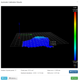
Mesh bed compensation probes the bed in a grid pattern, recording the height errors so that lack of flatness of the bed and in the plane of XY head movement can be compensated. I chose a grid covering X=25 to 175 and Y=25 to 275 (77 points).
The height map obtained is shown here. Clearly at least one of the desk surface and the printing plane is far from flat. The reported mean error of -0.38mm indicates that the height at the Z homing point close to the axis of the printer is significantly different from the mean height.
Adding a Panel Due
My initial thought was that adding an LCD control panel to this printer was not practical, because the whole body rotates. Eventually I noticed that the large carrying eye at the top of the printer does not rotate with the rest of it. So I designed and printed an adapter to allow my standard Panel Due enclosure to be mounted on top of that eye. I chose the smallest screen size (4.3 inch) because a larger screen would look out-of-place on a compact printer such as this.
Final thoughts
I have shown that it is possible to get acceptable prints from the Robotdigg SCARA Arm Printer after performing a number of mechanical and electronic upgrades. It is unlikely that this printer will ever provide speed or print quality to match those of my other printers. But the original cost of this printer was very low, and it offers a significantly longer build area in one dimension than my other printers do.
Update
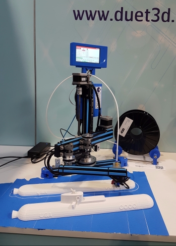
2017-09-30: We displayed this printer on the Duet3D stand at the TCT Exhibition from 26-28 September 2017 in Birmingham, UK. It turned out to be a crowd-puller because few people have seen a SCARA arm 3D printer.
We printed this desktop submarine scaled to 400mm length. To do this I changed the firmware configuration to specify a printable area of 200 x 400mm. The 200mm print depth is not available over the entire 400mm print width, but for this print it didn’t matter. The mesh bed probing algorithm is intelligent enough to skip points in the mesh that can’t be reached.
As this is an 11 hour print, we printed it over 2 days. We paused the print and powered down at the end of the first day, then resumed the print on the next day, using the resume-after-power-off facility that is supported as standard in RepRapFirmware for the Duets.
Second update
2017-10-10: As the printer was supplied, the proximal homing switch was positioned on a bracket that held it well forward of one end of the proximal arm – the end opposite the distal joint. This restricted the anticlockwise movement of the proximal arm, preventing the nozzle from moving very far to the right. I replaced the metal bracket by a printed block to set the microswitch back about 45mm to allow more movement. The print width is now another 65mm wider. If I re-route one of the cables, I think a further extension will be possible, giving a print width of up to 500mm. Not bad for a small printer!
Third update
2017-12-20: I noticed that the head movement sometimes still seemed slightly jerky. This happened even when the firmware was doing non-segmented positioning moves. So the problem had to lie with the motors. With a distal joint resolution of 100 steps/degree at x16 microstepping (increased from the original 80 steps/degree) and a distal arm length of 160mm, the resolution at the head is only about 36 microsteps/mm. The effective resolution due to the 71.111 proximal steps/degree is even worse, dropping to 13 microsteps/mm when the two arms are almost lined up. Increasing microstepping beyond x16 is generally not effective at increasing resolution, due to the reduction in incremental torque per microstep; and besides, there is always some variation in the size of microsteps. So I replaced the original 1.8deg proximal and distal motors with 0.9deg motors. I chose the “Compact but powerful motor” from E3D because it had the same 40mm length as the original motors and an appropriate current rating. As expected, this has made the movement smoother.

Hi mate, have you tried geckotek ez-stick with your IR sensor? I’m having issues with multiple triggering heights on a bare aluminium bed and that bed coating is reccomended by taulman for their nylons
No, I don’t have any geckotek.
This whole scara project it’s awesome